Part of Valve & Actuator Control Systems: The Complete BuildMEP Guide →
Practical HVAC valve selection guide
Cv or Kv connects a liquid design flow to the pressure drop across a valve, gives you a common basis for comparing products, and lets you check whether a proposed replacement will actually hold onto its control performance. Nominal pipe size alone can't answer any of that.
Decision brief
Cv and Kv measure flow capacity, not physical size. For a conventional water control valve, calculate the coefficient from the required design flow, the pressure drop assigned to the fully open valve, and the liquid specific gravity. Then compare actual catalog coefficients, recalculate the pressure drop of each candidate, and check valve authority, close-off pressure, connection, actuator, and operating limits.
Conversion: Kv = 0.865 × Cv, and Cv = 1.156 × Kv.
Use the simplified equations for
- Water and similar incompressible liquids
- Preliminary conventional HVAC control-valve sizing
- Catalog comparison and replacement screening
- Checking pressure drop at a known flow
Use the full standard or software for
- Gas, steam, flashing, cavitating, or two-phase service
- High-viscosity, non-Newtonian, slurry, or laminar flow
- Reducers, elbows, or tees attached close to the valve
- Severe-service and safety-critical selections
What Cv and Kv actually measure
Cv is the US customary valve flow coefficient. For a fully open valve, it's commonly stated as the flow of 60°F water in US gallons per minute needed to produce a pressure drop of 1 psi across the valve.
Kv expresses that same underlying capacity in metric units: cubic metres per hour of water at a pressure drop of 1 bar. The numbers come out different because the reference flow and pressure units are different—not because the valve itself has changed.
| Coefficient | Reference flow | Reference pressure drop | What a larger number means |
|---|---|---|---|
| Cv | US gpm of water | 1 psi | More flow capacity and less pressure drop at the same gpm |
| Kv | m³/h of water | 1 bar | More flow capacity and less pressure drop at the same m³/h |
Read Kv and Kvs carefully
In European valve data, Kvs usually identifies the rated Kv at full opening, while Kv can describe the coefficient at a particular valve position. Catalog conventions aren't consistent across brands, so confirm whether the published number is the full-open rated value, a preset value, or a value at part stroke before comparing products.
The liquid equations behind Cv and Kv
For a conventional valve handling an incompressible liquid under the simplified turbulent, non-choked conditions used in ordinary HVAC water checks:
Rearrange the relationship depending on what you're actually trying to find:
Q is the liquid flow in the units paired with the coefficient you picked, ΔP is the pressure drop across the valve, and SG is the liquid specific gravity relative to water at the applicable reference condition. For water, SG is usually just taken as 1 for preliminary HVAC calculations. For glycol or anything else, use verified project fluid data at the actual operating concentration and temperature.
The square-root equation is a screening tool, not the full control-valve standard
IEC 60534-2-1 and ANSI/ISA-75.01.01 add installed-condition, non-turbulent, pressure-recovery, choked-flow, and other corrections that this short equation doesn't capture. Don't use this page's calculator for compressible or severe service, and don't treat a preliminary coefficient as a manufacturer's final sign-off on a selection.
Converting Cv and Kv correctly
Kv = 0.865 × Cv
Cv = Kv / 0.865 ≈ 1.156 × Kv
Example: Cv 50 × 0.865 = Kv 43.25. Checking it the other way, 43.25 / 0.865 = Cv 50.
This conversion is purely a unit relationship — nothing manufacturer-specific about it. But a converted coefficient still doesn't prove two valves are interchangeable; you also need to check the published travel condition, flow characteristic, close-off rating, body arrangement, actuator, and installation conditions against the application.
Cv/Kv liquid valve calculator
Enter design flow, target valve pressure drop, and liquid specific gravity. The tool works out both Cv and Kv. If you also enter a candidate catalog coefficient, it calculates that candidate's actual pressure drop at design flow and its flow at the target pressure drop.
Calculator is waiting for JavaScript to initialize. On WordPress, use an HTML widget or preserve the script through an approved site asset.
Basis: simplified incompressible-liquid relationship. No Fp, Reynolds-number, cavitation, flashing, or choked-flow correction is applied.
For other design utilities, browse BuildMEP MEP tools and calculations.
Why same-size valves can have different Cv
Nominal valve size just defines the connection envelope; capacity comes down to internal geometry. Seat diameter, ball or plug geometry, trim, flow path, reduced-port construction, and the intended control characteristic can all shift Cv. So two DN50 or 2-inch valves can end up imposing very different pressure drops at the same flow.
That's exactly why a same-size replacement isn't automatically hydraulically equivalent. It comes up in both the Belimo EP050R+MP replacement guide and the broader Belimo valve alternatives guide: coefficient, flow range, close-off pressure, actuator function, and installation compatibility all need to be checked separately.
Cv, pressure drop, and valve authority are one selection problem
For a conventional pressure-dependent control valve, valve authority compares the fully open valve pressure drop at design flow against the pressure drop of the variable-flow circuit it's controlling:
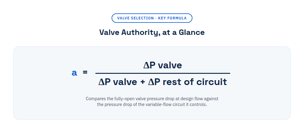
A very large Cv means a small valve pressure drop at design flow. That shrinks the valve's share of the circuit resistance and can distort the installed flow characteristic. This is the hydraulic link between Cv sizing and the differential-pressure and valve-authority checks.
Don't apply one authority target to every circuit
Published guidance and project specifications use different definitions and acceptable ranges for valve authority. State the formula you're using, define which circuit pressure losses are included, and check against the project or manufacturer criterion. A coefficient that delivers adequate flow can still fail the required authority, while a smaller coefficient can eat more head than the pump has available.
Worked selection: 80 gpm coil circuit
Take a conventional two-way control valve serving a water coil. This example is deliberately product-neutral — it's meant to walk through the decision sequence, not hand you a universal authority target.
1. Given design data
Design flow: 80 gpm
Liquid: water, SG = 1.00
Target fully open valve pressure drop: 4.0 psi
Pressure drop in the rest of the controlled circuit at 80 gpm: 6.0 psi
Available circuit differential pressure: 10.0 psi
2. Calculate the required coefficient
Cv = 80 × √(1 / 4) = 40.0
Kv = 0.865 × 40.0 = 34.6
Authority = 4.0 / (4.0 + 6.0) = 0.40
3. Compare catalog candidates at the same 80 gpm
| Candidate | Catalog Cv | Valve ΔP | Total circuit ΔP | Authority | Decision implication |
|---|---|---|---|---|---|
| A | 40 | 4.00 psi | 10.00 psi | 0.400 | Matches the stated design basis |
| B | 43 | 3.46 psi | 9.46 psi | 0.366 | Flow capacity passes; verify project authority criterion |
| C | 65 | 1.51 psi | 7.51 psi | 0.201 | Reject for this example: substantially lower authority |
| D | 35 | 5.22 psi | 11.22 psi | 0.465 | Reject: exceeds the stated available differential pressure |
Example selection: Candidate A, Cv 40
Candidate A is the only option here that reproduces the 4.0-psi valve allocation and fits the 10.0-psi available circuit differential pressure exactly. Candidate C is a good illustration of why a physically matching, higher-Cv valve isn't automatically a safe swap: its calculated authority comes in at roughly half the design value. Final procurement still needs verification of valve type, characteristic, close-off rating, pressure and temperature class, materials, leakage class, actuator, connection, and installed geometry.
When reducers or nearby fittings change the result
Rated coefficients come from defined test arrangements. If reducers, expanders, elbows, or tees sit close to the valve, their interaction with it changes the installed capacity. The standards capture this with a piping geometry factor, usually written Fp, alongside related installed-condition factors.
Don't assume the catalog Cv stays the effective installed coefficient, and don't try to guess a correction from nominal pipe sizes alone. Use IEC 60534-2-1, ANSI/ISA-75.01.01, the manufacturer's sizing software, or published product-specific factors. Emerson's sizing procedure specifically calls for Fp evaluation whenever reducers, elbows, or tees are directly attached to the valve.
How this changes for a PICV
A pressure-independent control valve combines a control element with differential-pressure regulation or electronic flow control. When the device is operating inside its published differential-pressure range, the regulator limits how much system-pressure variation actually affects flow. The primary selection is therefore usually driven by required design flow, available operating differential pressure, setting range, close-off capability, actuator/control function, and manufacturer limits—not by bolting the conventional Cv-and-authority workflow onto it unchanged.
Some manufacturers publish internal coefficients or describe the control section as having full authority, but those claims are product-specific. Follow the selected model's own data and commissioning procedure. See the BuildMEP PICV guide for the operating sequence and application boundary.
A repeatable Cv-based selection workflow
- Define the service. Record the liquid, concentration, operating temperature, specific gravity, design flow, minimum flow, and whether flashing, cavitation, high viscosity, or non-turbulent behavior is possible.
- Define the hydraulic boundary. Establish available differential pressure and the pressure losses included in the controlled circuit. Don't inherit an old valve's coefficient without checking the current system.
- Calculate the required coefficient. Use Cv with gpm and psi or Kv with m³/h and bar. Keep the unit system explicit and hold onto the design pressure-drop basis.
- Screen actual catalog candidates. Recalculate each candidate's pressure drop at design flow. A catalog value that simply exceeds the calculation isn't automatically the best choice.
- Check authority and available head. Confirm the selected coefficient neither drags authority below the stated criterion nor eats more differential pressure than the circuit can supply.
- Apply installed-condition corrections. Evaluate reducers and close-coupled fittings using the governing standard or manufacturer method, not an improvised percentage.
- Complete the product check. Verify characteristic, rangeability, close-off, leakage, pressure-temperature rating, materials, connection, fail position, actuator signal, stroke/rotation, and approvals.
- Commission the result. Measure differential pressure or flow at the design condition, confirm stable modulation, record settings, and compare the observed result against the design calculation.
Failure-mode register
| Mistake | Consequence | Typical field evidence | Correction |
|---|---|---|---|
| Comparing Cv directly with Kv | Capacity is misstated by about 15.6% | Calculated and catalog flows do not reconcile | Convert both candidates to one coefficient system |
| Selecting by nominal size only | Replacement pressure drop differs from the design | Low flow, overflow, hunting, or poor coil ΔT | Compare coefficient and recalculate candidate ΔP |
| Choosing the highest available coefficient | Low valve pressure drop and reduced authority | Useful modulation occurs over a small part of stroke | Size from design flow and assigned pressure drop |
| Ignoring specific gravity | Liquid capacity is calculated on the wrong density basis | Glycol circuit differs from the water calculation | Use verified operating-condition fluid data |
| Ignoring reducers or close fittings | Installed capacity differs from rated capacity | Measured ΔP or flow disagrees with the simple equation | Apply the standard/manufacturer Fp method |
| Using the liquid shortcut for steam or gas | Compressibility and choked-flow effects are omitted | Severe sizing error, noise, or capacity limitation | Use the applicable IEC/ISA equations and manufacturer software |
| Treating PICV selection as conventional Cv sizing | Minimum operating ΔP or setting range can be missed | Flow limit is not maintained across system conditions | Select and commission from the PICV manufacturer's published envelope |
Design and replacement verification
- Confirm whether each catalog number is Cv, Kv, Kvs, a preset value, or a full-open value.
- Record design and minimum flow, liquid, concentration, temperature, and specific gravity.
- Define the available differential pressure and the circuit used in the authority calculation.
- Calculate required coefficient and candidate pressure drop in one consistent unit system.
- Check installed-condition corrections for reducers and close-coupled fittings.
- Verify authority, available head, close-off rating, characteristic, rangeability, and leakage requirement.
- Compare actuator voltage, signal, fail position, feedback, stroke or rotation, timing, and mounting.
- Witness commissioned differential pressure or flow and stable response through the required operating range.
- Document the coefficient basis, conversions, assumptions, selected model, and manufacturer confirmation in the submittal or compliance matrix.
Standards and evidence trail
- IEC 60534-2-1:2011, Industrial-process control valves—Flow capacity—Sizing equations for fluid flow under installed conditions—scope and governing equations for incompressible and compressible flow under installed conditions; IEC lists a stability date of 2028.
- ANSI/ISA-75.01.01-2012 (IEC 60534-2-1 MOD)—US adoption and modification of the control-valve flow-capacity sizing framework.
- Emerson, Control Valve Handbook, 6th edition—liquid sizing sequence, flow coefficients, installed piping geometry factor, and application checks.
- Emerson/Fisher Control Valve Sizing Procedures—Kv = 0.865 Cv conversion and Fp treatment for attached fittings.
- Belimo, What Is Cv and How Do I Calculate It?—HVAC definition, water sizing equation, and selection implications.
- Siemens, Hydronics in Building Systems, 2025—valve-authority definition and the relationship between valve and variable-circuit pressure drop.
Focused questions
Is a higher Cv always better?
No. A higher Cv means more capacity and less pressure drop at a stated flow. Push it too high for a conventional modulating application and you can drag down valve authority, squeezing useful control into a small slice of the stroke.
Does Cv change with valve position?
Yes. The coefficient shifts as the valve moves. The relationship between travel and coefficient is what defines the valve's inherent characteristic — linear, equal-percentage, or quick-opening. Make sure a catalog comparison uses coefficients at equivalent positions—normally the rated full-open value for initial sizing.
Can the water equation be used for glycol?
You can plug in specific gravity for a preliminary incompressible-liquid calculation, but concentration and temperature also affect viscosity and vapor pressure. Use verified fluid properties and manufacturer sizing software once those effects might actually matter.
Can a replacement valve have a slightly different Cv?
Possibly, but it's a decision you calculate, not one you eyeball. Recompute pressure drop and authority at the required flow, then run through the full hydraulic, mechanical, controls, and ratings checklist. “Close” isn't a universal percentage.
Part of a BuildMEP guide
This article is one step in Valve & Actuator Control Systems: The Complete BuildMEP Guide. It walks through valve sizing first, then actuator selection, plus a submittal checklist for the complete assembly.