
Every buried pressure pipe wants to straighten itself out. At every bend, tee, or dead end, internal pressure pushes against the fitting wall, and if nothing holds that fitting in place, the joint pulls apart, soil erodes around it, and you get a blowout that’s expensive to find and worse to fix once it’s under a slab or a road. A thrust block is the plain concrete answer: a mass of concrete poured against undisturbed soil at the fitting, sized so the soil’s own bearing capacity resists the thrust before the joint does.
This is a core calculation for anyone laying ductile iron or PVC water, fire, or irrigation mains with mechanical or push-on joints — and it’s one a lot of people size by eye or copy from an old project rather than work through. Below is the logic, the numbers, and a free calculator and Excel sheet so you don’t have to do it by hand every time.
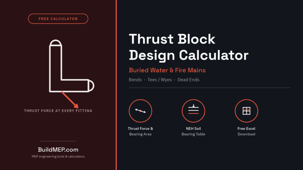
Thrust Block Design Calculator
Bends, tees/wyes, and dead ends — based on T = 2PA sin(Δ/2) for bends and T = PA for tees/dead ends, with a 1.5 safety factor applied to the required bearing area.
Use the actual OD from the pipe submittal, not the nominal size.
Use hydrostatic test pressure if higher than working pressure.
Use a site-specific geotechnical value where you have one.
8 in is a common minimum for cast-in-place blocks – confirm against your project spec.
—
—
—
Preliminary sizing only, based on the standard thrust-force method (T = 2PA sin(Δ/2) for bends, T = PA for tees/dead ends) and USDA-NRCS National Engineering Handbook Part 636, Ch. 52, Table 52-6 reference soil bearing values. Not a substitute for a project-specific geotechnical report or your governing design standard — verify before finalizing concrete dimensions.
Download the Excel version (free, angle + tee/wye/dead-end, no macros)
Do you actually need one?
Thrust blocks matter when the pipe joints themselves can’t resist axial pull-apart force — that’s bell-and-spigot push-on joints and most mechanical joints. If you’re running butt-fused or electrofused HDPE, the joint is already stronger than the pipe wall around it, so the line is self-restrained and a conventional thrust block usually isn’t needed at all, though anchor blocks can still show up at valve vaults or where the pipe transitions to a flanged connection. Restrained-joint ductile iron (boltless or gasket-restrained) is the other common way around this, usually chosen when there isn’t enough clear ground around a fitting to build a block of the required size — common in congested utility corridors or where you can’t disturb an existing structure. Thrust blocks are the default when none of that applies: unrestrained joints, open ground, and a soil that can bear the load.
The physics, in plain terms
Internal pressure acts on every square inch of a pipe’s cross-section. In a straight run that force cancels out — it’s pushing equally in both directions. At a bend it doesn’t cancel, because the pipe changes direction; the unbalanced portion of that force is the thrust you have to resist. At a tee branch or a dead end, there’s no cancellation at all — the full line pressure pushes straight out against whatever’s in its way.
Bends: T = 2 × P × A × sin(Δ/2)
Tees, in-line valves, dead ends, caps: T = P × A
Where T is the resultant thrust force (lb), P is the internal design pressure (psi) — use the system’s test pressure, not just the working pressure, since that’s the worse case — A is the pipe’s cross-sectional area based on its actual outside diameter (in²), and Δ is the fitting’s true deflection angle in degrees. Use the pipe’s real OD from the manufacturer’s submittal, not the nominal size; on a 10- or 12-inch main the difference is enough to matter.
Once you have the thrust force, the required bearing area is:
A_required = (T ÷ q_allow) × SF
q_allow is the soil’s allowable bearing pressure (lb/ft²) at the depth to the center of the block, and SF is a safety factor — 1.5 is standard practice across the municipal design standards that publish this method, and it’s worth keeping even when a project spec doesn’t explicitly call for it, since soil bearing values are themselves already an approximation.
Soil bearing pressure: don’t guess
This is the number most people get wrong, because it’s tempting to pick something that makes the block smaller. Where a geotechnical report or site-specific soil test exists, use it — it overrides any table. Where one doesn’t, Table 52-6 of the USDA-NRCS National Engineering Handbook (Part 636, Chapter 52) gives commonly used reference values for undisturbed natural soil, by depth of cover to the center of the block:
| Natural soil material | 2 ft | 3 ft | 4 ft | 5 ft |
|---|---|---|---|---|
| Sound bedrock | 8,000 | 10,000 | 10,000 | 10,000 |
| Dense sand and gravel (θ≈40°) | 1,200 | 1,800 | 2,400 | 3,000 |
| Dense fine to coarse sand (θ≈35°) | 800 | 1,200 | 1,650 | 2,100 |
| Silt and clay mixture (θ≈25°) | 500 | 700 | 950 | 1,200 |
All values in lb/ft². These are reference starting points for a preliminary design, not a substitute for an actual geotechnical report on a real project — disturbed, saturated, or previously excavated soil (common in a trench that’s been backfilled once already) bears nowhere near these numbers, which is exactly why the block has to sit against undisturbed soil, not backfill.
Worked example — 90° bend
A 10-inch ductile iron fire main (11.10 in actual OD per the pipe submittal) carries a 150 psi design pressure through a 90° horizontal bend, buried with 4 ft of cover in dense fine-to-coarse sand.
- A = π/4 × 11.10² = 96.8 in²
- T = 2 × 150 × 96.8 × sin(45°) = 20,528 lb
- q_allow (sand, 4 ft) = 1,650 lb/ft²
- A_required = (20,528 ÷ 1,650) × 1.5 = 18.7 ft²
- At a common minimum block thickness of 8 inches around the pipe: V = 18.7 × 0.667 ft = 12.4 ft³ ≈ 0.46 cu yd of concrete
Drop the same main down to a 45° bend and the thrust — and the block — roughly halves, because sin(22.5°) is a lot smaller than sin(45°). The single biggest lever on thrust block size isn’t pipe size, it’s how many smaller-angle fittings you use instead of one large one.
Tee branch, same main: a 6-inch branch (6.90 in OD) off that same 150 psi, 4 ft-cover main: T = P × A = 150 × 37.4 = 5,609 lb, giving A_required = (5,609 ÷ 1,650) × 1.5 = 5.1 ft² and roughly 0.13 cu yd of concrete — noticeably smaller, because there’s no sin(Δ/2) term knocking the force down, but it’s acting on a much smaller branch area.
Mistakes that actually cause failures in the field
Pouring against disturbed soil. The whole calculation assumes the block bears against undisturbed ground. If the trench was over-excavated at the fitting and backfilled, that backfill doesn’t have anywhere near the bearing capacity the table assumes — hand-trim back to undisturbed material even if it means a wider excavation.
Backfilling before the concrete has cured. Loading a green thrust block with backfill and compaction equipment before it has enough strength is a common way for an otherwise correctly-sized block to fail anyway. Follow the mix’s minimum cure time before backfilling and testing the line.
Wrapping the fitting in polyethylene first. Standard practice on ductile iron for corrosion protection, but if the poly sleeve or any bond-breaker gets between the concrete and the fitting itself, you’ve built a block that isn’t actually gripping what it’s supposed to restrain. Keep the bare fitting in direct contact with the concrete; wrap around the block, not between it and the pipe.
Skipping the hydrostatic test load case. Design the block for the test pressure, not just the working pressure — a line tested at 1.5× working pressure sees thrust forces well above what it’ll see in daily service, and that’s the load case that should size the block.
Assuming a tee doesn’t need its own block because the run continues straight through. The branch still sees full, uncancelled thrust in its own direction and needs its own bearing area — it isn’t covered by whatever block exists on the main run.
Standards and references
This method follows the standard approach published across most US municipal and utility water design standards (thrust = pressure × resisting area, resolved by fitting geometry) and the USDA-NRCS National Engineering Handbook’s soil bearing reference table for buried pipelines. It’s a widely accepted preliminary design method — always confirm against your project’s governing design standard, local water authority requirements, and an actual soils report before finalizing concrete dimensions on a real job.
Related on BuildMEP
- Fire Hydrant System Method Statement — installation, testing and commissioning of the buried main this calculator sizes blocks for.
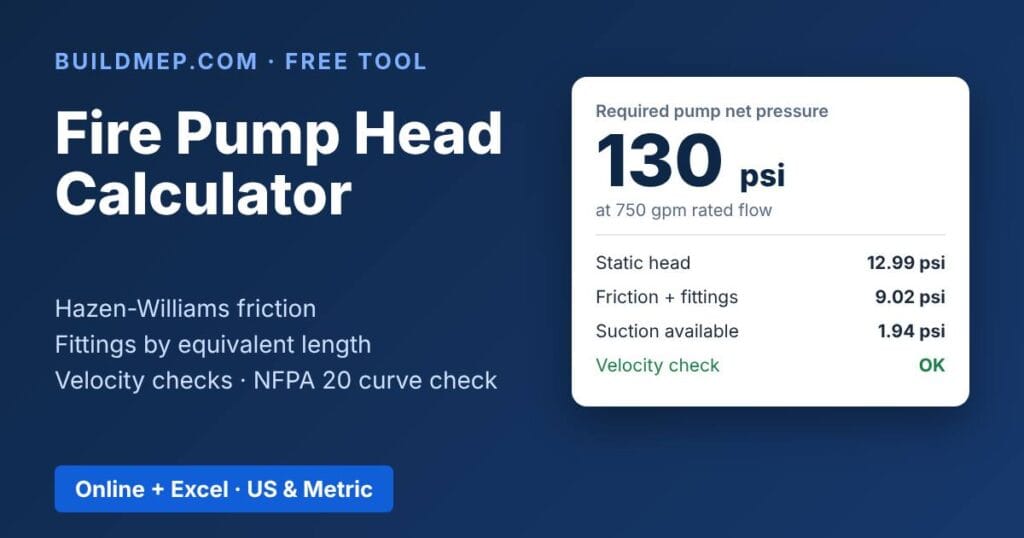
- Fire Pump Head Calculator — free online + Excel, for sizing the pump feeding the same main.
- Domestic Water Pipe Sizing Guide — WSFU, pressure loss and velocity for the pipe upstream.
- Fire Protection Systems: The Complete BuildMEP Guide — the full fire protection cluster.