Fire & Smoke Damper Selection — Practical Fire Protection Design Guide
Fire dampers , smoke dampers , combination fire / smoke dampers , and ceiling radiation dampers . All of these are used to protect openings in rated construction for fire protection . However , they are not all the same . This guide explains the function of each type, where each type is typically used, what the UL rating means and common installation errors that often cause problems during UL inspection .
A fire damper closes in response to heat and limits flame passage through a fire-resistance-rated assembly. A smoke damper controls smoke movement and is normally operated by the fire alarm or smoke-control system. A combination fire/smoke damper performs both functions in one listed assembly. A ceiling radiation damper protects a listed floor/ceiling or roof/ceiling assembly from excessive heat transfer through an opening.
The final selection is not based on damper type alone. You must also check the barrier being penetrated, applicable IBC section and exceptions, hourly rating, leakage class, velocity/pressure rating, mounting arrangement, and the manufacturer’s listed installation instructions.
Why this is worth getting right
Life safety dampers are often overlooked because under normal conditions they appear as simply another HVAC piece of equipment. But during a fire they are integrated into the fire and smoke protection system of the building.
The 1980 fire at the MGM Grand Hotel is a cautionary tale of the importance of smoke control and operable HVAC safety components. Significant deficiencies in smoke-control features, such as dampers that were not operable, were recorded during investigations. The lesson to be learned is: If a damper can’t close, seal and respond properly, it is not being used as designed.
The four damper types
Fire damper
Installed in an air distribution system to close automatically when heat is detected and restrict the passage of flame. Fire dampers are tested to UL 555 and are available with 1½-hour or 3-hour ratings.
Smoke damper
Used to control the movement of smoke. Smoke dampers are normally actuated by the fire alarm or smoke-control system rather than waiting for a fusible link to operate. They are tested to UL 555S and carry leakage, velocity, pressure, and temperature ratings.
Combination fire/smoke damper
Provides both fire-damper and smoke-damper functions in one listed assembly. It is evaluated to both UL 555 and UL 555S and is typically used where the code requires both fire and smoke protection at the same opening.
Ceiling radiation damper
Protects openings in listed floor/ceiling or roof/ceiling assemblies by limiting heat transfer through the ceiling membrane. Ceiling radiation dampers are evaluated to UL 555C and are not interchangeable with ordinary fire dampers.
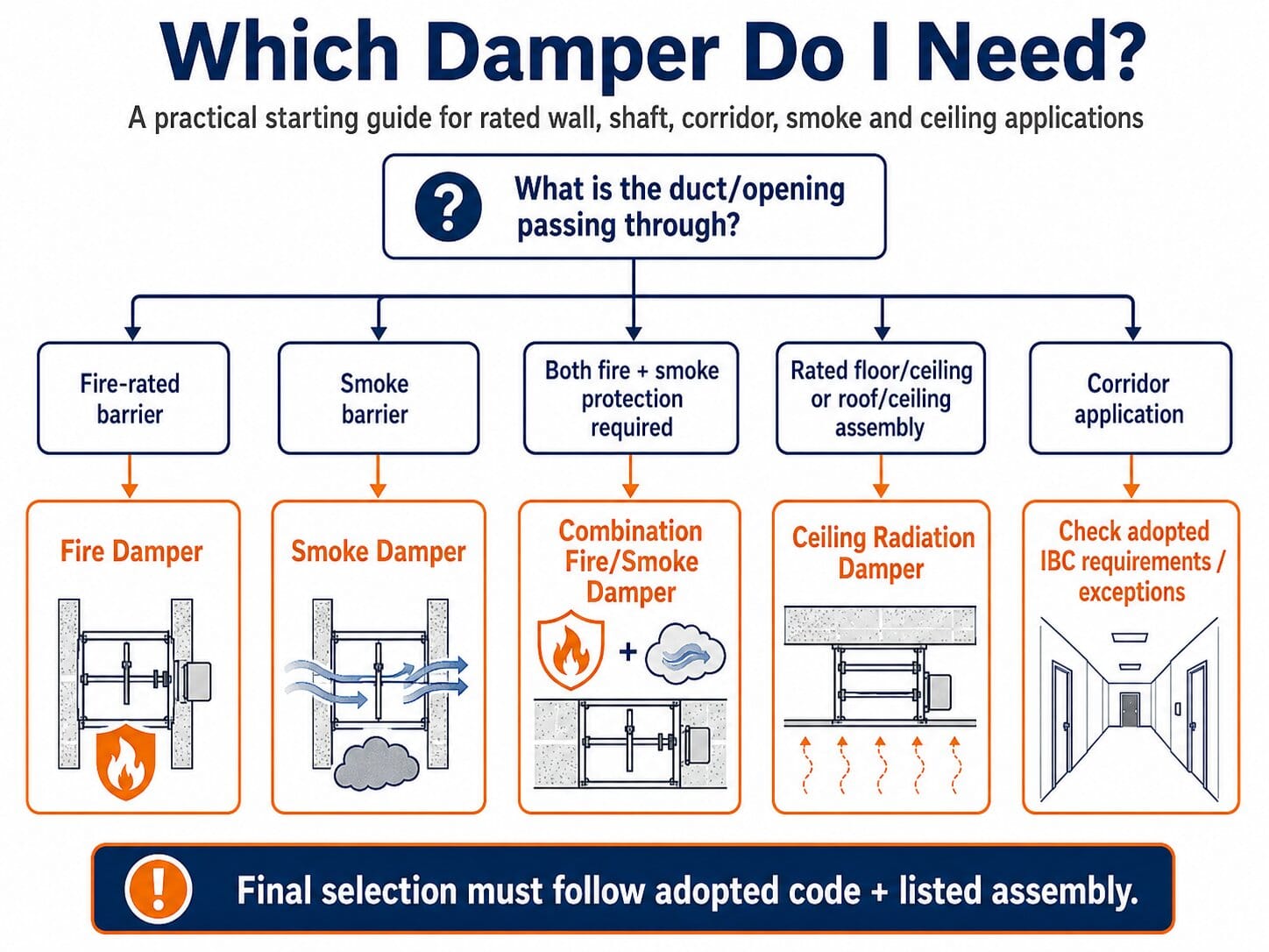
Which damper should you check first?
- Penetrating a fire-resistance-rated wall, floor, or partition? Check whether a fire damper is required.
- Penetrating a smoke barrier or an air-transfer opening in a smoke partition? Check whether a smoke damper is required.
- Both fire and smoke protection required at the same opening? A listed combination fire/smoke damper is commonly used.
- Opening in a rated floor/ceiling or roof/ceiling assembly? Check whether the tested assembly requires a ceiling radiation damper.
- Corridor application? Check the adopted IBC carefully. Corridor-damper provisions and exceptions may apply.
Where each type is commonly required
IBC Section 717.5 identifies where fire and smoke dampers are required, but it is not a simple one-row-per-barrier rule. Each subsection contains conditions and exceptions, so the table below should be used only as a starting point.
| Barrier / application | Typical starting point | What to verify |
|---|---|---|
| Fire wall | Fire damper | Applicable IBC subsection and exceptions |
| Fire barrier | Fire damper | Whether smoke protection is also required, such as at certain horizontal exits |
| Shaft enclosure | Fire and smoke protection commonly required | IBC shaft-penetration requirements and listed exceptions |
| Fire partition | Fire damper in many applications | Corridor, occupancy, duct arrangement, and other exceptions |
| Smoke barrier | Smoke damper | Specific exceptions in the adopted IBC |
| Smoke partition | Smoke damper at certain air-transfer openings | Do not assume every duct penetration requires one; check the applicable IBC provision |
| Exterior wall | Fire damper may be required | Exterior-wall fire-resistance requirements and applicable exceptions |
| Corridor | Fire, smoke, combination, or corridor damper depending on the construction | Corridor classification, wall rating, ceiling construction, and adopted-code exceptions |
Where an assembly requires both fire and smoke protection, the IBC permits a listed combination fire/smoke damper or separate listed fire and smoke dampers, subject to the applicable installation requirements.
Hourly fire-resistance rating
The fire-damper hourly rating is linked to the rating of the assembly it protects. The normal IBC relationship is:
| Fire-resistance rating of assembly | Minimum fire-damper rating |
|---|---|
| Less than 3 hours | 1½ hours |
| 3 hours or more | 3 hours |
For example, a 2-hour rated wall typically uses a 1½-hour fire damper, while a 3- or 4-hour rated assembly requires a 3-hour damper, subject to the applicable listing and code provisions.
UL qualifications you should actually check
Two dampers can both be labelled “fire/smoke damper” and still be unsuitable for the same application. The UL classification includes several separate ratings.
Fire dampers — UL 555
Check the hourly rating, static or dynamic classification, mounting position, installation orientation, and the velocity/pressure rating where the damper is dynamically rated.
Smoke dampers — UL 555S
Check leakage class (see our damper leakage class guide for what Class I and II actually mean and why the test pressure matters), velocity rating, pressure rating, temperature rating, actuator arrangement, and required fail position.
Combination fire/smoke dampers
Check both sets of qualifications. The fire and smoke functions are part of the same listed assembly, so hourly rating, leakage, pressure, velocity, temperature, mounting, and actuator requirements all matter.
Ceiling radiation dampers — UL 555C
Use only where the tested floor/ceiling or roof/ceiling assembly allows that damper. Selection must follow the listed assembly rather than simply matching duct size.
Smoke-damper leakage class
UL 555S leakage classification tells you how much air can leak through the closed smoke damper at a specified test pressure. Lower leakage is better.
| Leakage class | Maximum leakage at 4 in. w.g. | Relative tightness |
|---|---|---|
| Class I | 8 cfm/ft² | Tightest of the three common classes |
| Class II | 20 cfm/ft² | Intermediate |
| Class III | 80 cfm/ft² | Highest permitted leakage of these three classes |
Do not convert these leakage classes directly into “minutes until a room fills with smoke” unless room volume, pressure differential, leakage area, and the rest of the smoke-control design are explicitly defined.
Static vs dynamic fire dampers
This distinction depends on the HVAC operating condition during a fire:
- Static fire damper: intended for systems where airflow is shut down when the damper closes.
- Dynamic fire damper: tested to close against airflow and pressure within its listed ratings.
Do not assume every fan shuts down in a fire. Smoke-control and other engineered sequences may keep fans operating. The damper classification must match the approved sequence of operation.
What makes an installation acceptable?
- The rated assembly — the wall, floor, shaft, partition, or ceiling assembly must be the construction assumed by the design.
- The listed damper — the selected model must carry the required UL classification and application ratings.
- The listed installation method — sleeve, clearances, retaining angles, duct connection, access, fasteners, and other details must follow the manufacturer’s tested installation instructions.
Installation details that commonly cause problems
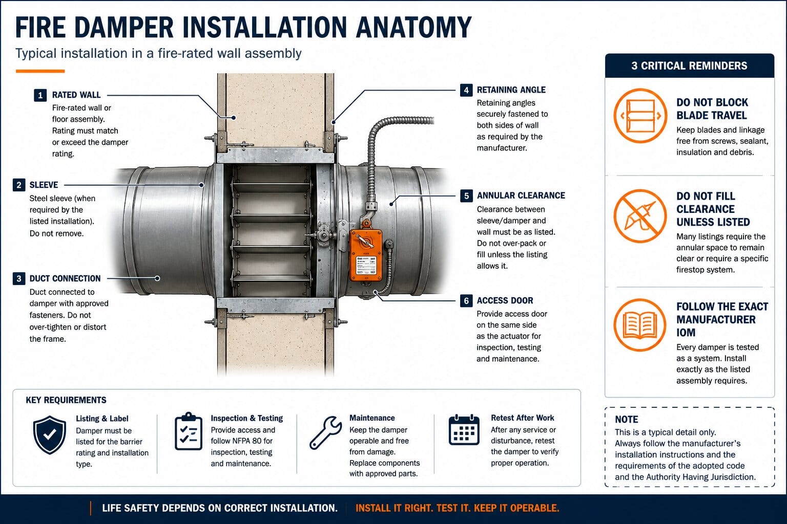
Sleeve
Many listed installations use a steel sleeve with minimum gauge and maximum projection limits. These dimensions are listing-specific. Do not apply sleeve dimensions copied from one manufacturer’s detail to another damper without checking the exact IOM.
Retaining angles
Two-sided, single-sided, and in some cases three-sided retaining-angle methods may be listed. Attachment spacing, minimum angle size, and whether the angle is fastened to the wall vary by installation method.
Expansion clearance
The annular clearance around the sleeve allows the assembly to accommodate movement during fire exposure. Do not grout, caulk, or firestop the gap unless the manufacturer’s tested installation detail specifically permits it.
Duct connection
Where a breakaway connection is required, it must be installed exactly as listed. A rigid duct connection can transfer forces into the damper and rated barrier during a fire.
Access
Provide enough access to inspect, test, reset, and service the damper, heat-responsive device, actuator, linkage, and other listed components. Access-panel size and labelling should follow the applicable NFPA requirement, code, and manufacturer instructions for the project edition.
Actuator
New UL 555S smoke and combination fire/smoke damper assemblies are supplied with actuators as part of the listed arrangement. If an existing actuator has to be replaced, use an approved replacement procedure and compatible listed actuator — not an arbitrary HVAC actuator chosen only by torque. For normal HVAC actuator sizing principles, see the BuildMEP actuator torque sizing guide; life-safety damper actuator replacement still has to follow the damper manufacturer’s approved procedure.
Installations that often fail inspection
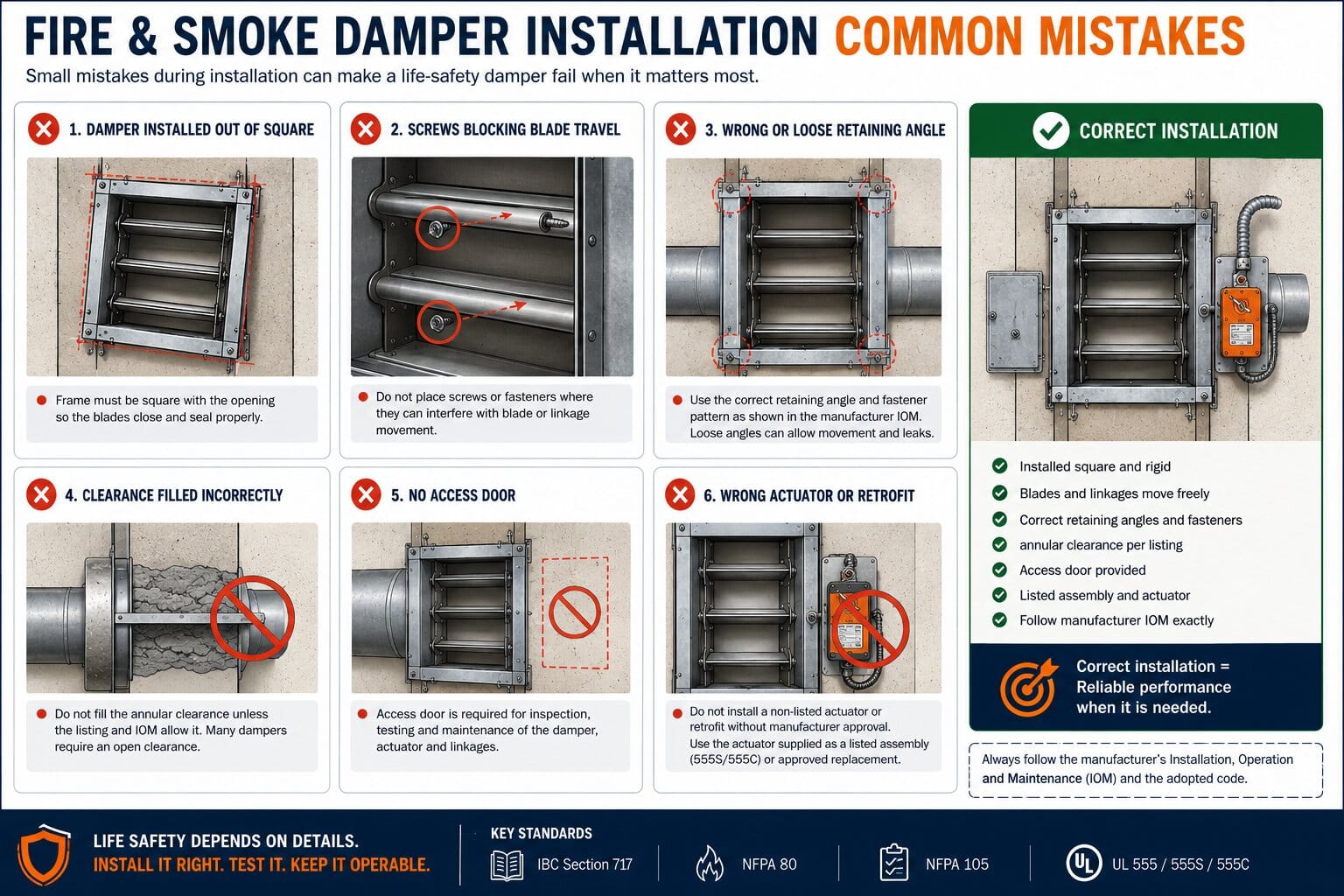
- Damper installed racked or out of square — blades or curtain may bind before full closure.
- Screws or fasteners interfering with the blade path — a simple installation error that can physically stop operation.
- Field bending or cutting of the damper frame or blades — changes the tested configuration.
- Incorrect retaining-angle arrangement — especially when a contractor mixes details from different models.
- Annular space filled without an approved detail — can prevent the movement allowed by the listing.
- No practical access for inspection and reset — a damper hidden above services may technically exist but still be impossible to maintain.
- Wrong actuator replacement — matching voltage or torque alone is not enough for a life-safety assembly.
- Failure to follow the exact IOM — still one of the easiest ways to turn a listed product into a noncompliant installation.
Testing and maintenance
Fire and smoke dampers are not “install and forget” equipment. NFPA 80 and NFPA 105 require inspection and operational testing after installation and at periodic intervals.
| Damper type | Typical periodic requirement | Important note |
|---|---|---|
| Fire damper | Test after installation; again 1 year after acceptance, then typically every 4 years | Hospitals commonly use a 6-year interval after the first-year test |
| Smoke damper | Operational testing after installation/commissioning; again 1 year after acceptance, then typically every 4 years | Hospitals commonly use a 6-year interval after the first-year test |
| Combination fire/smoke damper | Must satisfy the applicable fire- and smoke-damper inspection/testing requirements | Follow NFPA 80, NFPA 105, adopted code, and the listed assembly instructions |
During testing, verify that the damper moves through its required travel without obstruction and that the associated actuator, detector, switch, indication, and control sequence respond correctly. If you are also coordinating fire-detection containment work, see our fire detection conduit installation method statement. The exact procedure depends on whether the damper is static, dynamic, smoke-control related, or combination type.
Practical selection workflow
1. Identify the barrier → fire wall, fire barrier, shaft, partition, smoke barrier, smoke partition, corridor, floor/ceiling assembly, etc.
2. Check the adopted IBC section and exceptions → do not select from a generic table alone.
3. Choose the damper category → fire, smoke, combination fire/smoke, ceiling radiation, or corridor damper where applicable.
4. Confirm ratings → hourly rating, leakage class, velocity, pressure, temperature, mounting position, and dynamic/static classification.
5. Check the approved sequence → fan shutdown, smoke-control mode, fail position, detector signal, and actuator operation.
6. Install exactly as listed → sleeve, retaining angles, clearance, duct connection, access, and actuator arrangement.
7. Test and document → verify operation before handover and keep records for future periodic inspection.
Standards and authoritative references
- International Building Code (IBC), Section 717 — ducts, air-transfer openings, damper locations, and exceptions. Always use the edition adopted by the project jurisdiction.
- UL Solutions — Dampers Marking and Application Guide — practical guidance covering UL-listed fire, smoke, combination, and ceiling dampers, including ratings and installation considerations.
- UL 555 — Standard for Fire Dampers. See the UL application guide above for marking and application guidance.
- UL 555S — Standard for Smoke Dampers. See the UL application guide above for leakage, airflow, and application guidance.
- UL 555C — Standard for Ceiling Dampers / ceiling radiation dampers.
- NFPA 80 — installation, inspection, testing, and maintenance requirements applicable to fire dampers and other opening protectives.
- NFPA 105 — requirements for smoke-door assemblies, smoke dampers, and related opening protectives.
- NFPA — Basics of Fire and Smoke Damper Installations — useful overview of damper applications and installation considerations.
- NFPA — Fire and Smoke Damper ITM — inspection, testing, and maintenance overview.
Code section numbering, exceptions, and testing language can change between editions. Always verify the edition adopted by the project jurisdiction and the listing/IOM for the exact damper model before using this guide for a permitted design or inspection decision.
Related BuildMEP guides
- Valve and Damper Actuator Torque Sizing Guide — useful when checking ordinary HVAC damper actuator torque, spring return, and replacement sizing.
- Siemens GCA166.1E vs GCA161.1E Damper Actuators — a practical example of checking actuator control, feedback, and replacement compatibility.
- Method Statement for Conduit Laying in Fire Detection Systems — useful for fire-alarm containment coordination and site execution.
- Best CO and NO₂ Sensors for Parking Garages — related life-safety/BMS guidance for gas detection and ventilation control.
Frequently asked questions
Do I have to fill the annular space around a fire damper?
Not as a general rule. The clearance is part of the listed installation and often exists to accommodate movement. Only seal or firestop it where the exact manufacturer’s tested installation detail permits that method.
Can I use a fire damper instead of a ceiling radiation damper?
No. They are evaluated for different functions and different assemblies. A fire damper is tested to UL 555, while a ceiling radiation damper is tested to UL 555C for use in approved floor/ceiling or roof/ceiling systems.
Do all smoke partitions need smoke dampers?
No. The requirement depends on the type of opening and the applicable IBC provision. In particular, IBC provisions address smoke dampers at certain air-transfer openings through smoke partitions. Check the adopted section and exceptions rather than assuming every duct penetration needs one.
Can I replace a smoke-damper actuator in the field?
Yes, but not with just any actuator. Use a manufacturer-approved or otherwise accepted replacement procedure and a compatible actuator that preserves the listed life-safety function of the assembly.
What is the practical difference between Class I and Class III smoke leakage?
At the same UL 555S test pressure, Class I permits much less leakage than Class III. That means a Class I damper is substantially tighter, but the actual smoke movement in a building still depends on pressure differences, opening area, smoke-control strategy, and the rest of the system.
Should I choose a static or dynamic fire damper?
Match the damper to the approved HVAC sequence. If airflow is present when the damper must close, use a damper listed for the required dynamic velocity and pressure. If the system is shut down before closure, a static application may be acceptable where permitted by the design and code.