Practical HVAC Controls Guide
You have a failed actuator in front of you and a replacement that “looks about right.” Before fitting it, pause: the label may match the voltage and control signal while the actuator is still too weak—or wrong for the type of motion required.
For an air damper, start with the damper area and the damper manufacturer’s torque loading, then include an appropriate sizing allowance. For a ball or butterfly valve, use the valve manufacturer’s operating-torque data. For a globe valve or other rising-stem valve, select by linear thrust, stroke and close-off differential pressure—not by rotary torque. (For how close-off differential pressure is actually sized, and how it connects to valve authority and PICV selection, see our differential pressure control guide and our what is a PICV guide.)
That distinction saves a surprising amount of confusion. “Actuator size” does not always mean the same thing: dampers and quarter-turn valves rotate, while globe-valve stems travel in a straight line.
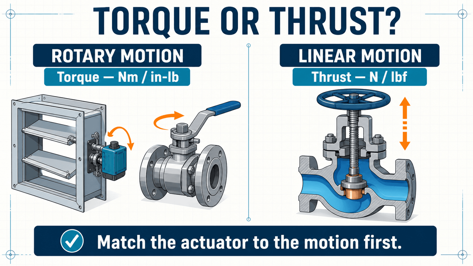
First decide: torque or force?
Use torque (Nm or in-lb)
Air dampers, ball valves and butterfly valves use rotary motion. The actuator must produce enough turning moment throughout the required travel.
Use force/thrust (N or lbf)
Globe valves and many PICV assemblies use linear stem movement. Check actuator thrust, usable stroke, stem connection and the valve/actuator assembly’s close-off rating.
Damper actuator torque: the practical method
The best input is always the damper manufacturer’s published torque requirement at the actual operating condition. Once you have it, the basic calculation is simple:
For rectangular dampers, area is width × height. For round dampers, area is π × diameter² ÷ 4. Keep the units consistent: use square metres with Nm/m², or square feet with in-lb/ft².
The sizing factor covers reasonable uncertainty such as linkage loss, small misalignment, dirt and ageing. Siemens, for example, shows total torque as torque rating × area divided by a 0.80 safety factor—the same numerical result as multiplying by 1.25. That is a useful manufacturer example, not permission to apply 25% blindly to every product. Follow the selected damper and actuator manufacturer’s instructions.
What if the damper data is missing?
Use a generic factor only for a preliminary estimate. Belimo’s retrofit guidance includes examples using 5 in-lb/ft² for an opposed-blade rectangular damper with edge seals below 1,000 fpm, and 10 in-lb/ft² for a round damper in the example condition. Those numbers are not universal ratings. Blade type, seals, bearings, velocity, static pressure and linkage can change the load materially.
| Input | Why it matters | Where to confirm it |
|---|---|---|
| Damper dimensions | Sets the blade area being driven | Approved drawing or field measurement |
| Torque loading | Captures the damper construction and operating load | Damper manufacturer |
| Air velocity / pressure | Higher aerodynamic load may increase torque | Design schedule and damper data |
| Linkage and shaft condition | Poor alignment or worn parts add resistance | Physical inspection |
| Fail-safe requirement | Determines spring-return or electronic fail-safe duty | Sequence of operation / life-safety design |
Damper torque estimator
Enter the dimensions and a torque-loading value from the damper manufacturer. The tool reports the calculated design torque and the next practical selection should be an actuator whose minimum rated torque meets or exceeds it.
Preliminary selection aid only. It does not account for every blade, seal, pressure, linkage or life-safety condition. Verify the final actuator against the damper manufacturer’s torque data and the project sequence.
Worked example: rectangular opposed-blade damper
Assume a 1,000 × 800 mm damper. Its area is 0.80 m², or about 8.61 ft². If the damper manufacturer confirms 5 in-lb/ft² and its instructions permit a 1.25 sizing factor:
The actuator’s guaranteed minimum torque must be at least 6.08 Nm. In practice, select the next suitable manufacturer rating and then check shaft size, mounting, control signal, fail position and enclosure. Do not choose from the nominal torque number alone.
Round-damper example
A 500 mm round damper has an area of approximately 0.196 m², or 2.11 ft². Using an illustrative 10 in-lb/ft² factor and 1.25 sizing factor gives 26.4 in-lb, or 2.98 Nm. Again, the factor must match the actual damper construction and operating condition.
Nm ↔ in-lb torque converter
1 Nm = 8.8507458 in-lb. Torque units are written in-lb or lbf·in; they are not the same as energy.
Valve actuators: where the damper formula stops
Ball and butterfly valves
These are quarter-turn valves, so torque is the relevant mechanical output. But multiplying valve size by a generic factor is not a reliable selection method. Use the valve manufacturer’s breakaway, running and seating torque—or its tested valve/actuator selection table—at the actual differential pressure, media, temperature and operating frequency. Bray’s selection guidance, for example, applies separate application, design and frequency factors and explicitly notes that its listed valve torque requirements do not already include safety factors.
Globe valves and linear PICV actuators
Here the actuator pushes or pulls the stem. The pressure difference across the plug creates a force; packing friction adds more resistance. Select an approved valve-and-actuator combination by thrust, stroke and close-off differential pressure. Belimo’s technical explanation describes close-off pressure as a property of the complete valve, linkage and actuator combination—not the actuator in isolation.
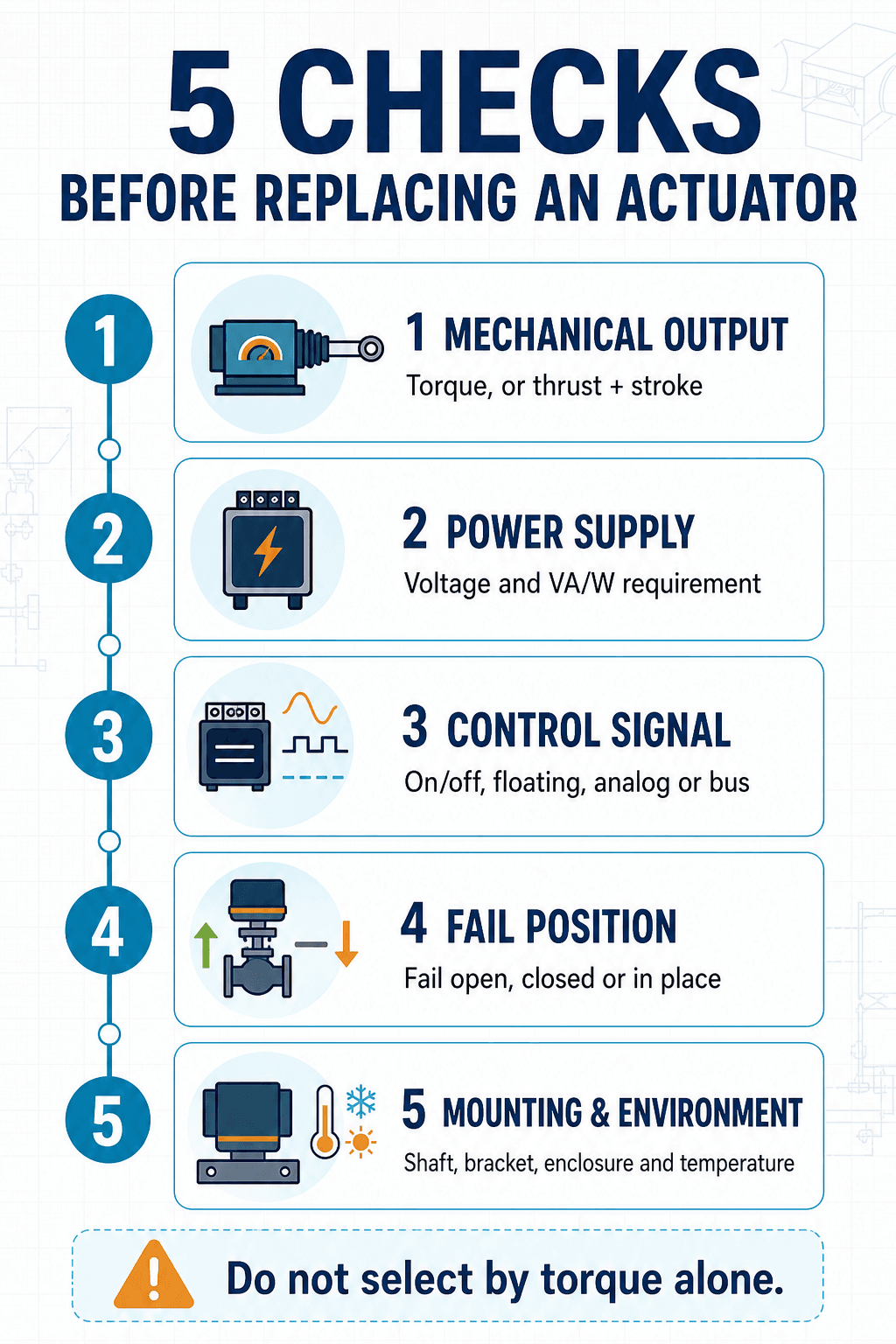
Replacement actuator checklist
| Check | Record before ordering | Common miss |
|---|---|---|
| Mechanical output | Minimum torque, or thrust plus stroke | Matching only the old actuator’s physical size |
| Power supply | 24 VAC/DC, 120 VAC, 230 VAC; VA/W requirement | Assuming all “24 V” devices accept AC and DC |
| Control | On/off, 3-point/floating, 0–10 V, 2–10 V, 4–20 mA, or bus protocol | Confusing feedback signal with command signal |
| Fail position | Fail open, fail closed, fail in place; spring or electronic fail-safe | Copying the old rotation without checking the sequence |
| Travel and timing | Rotation/stroke, running time, spring-return time | Ignoring smoke-control or process timing |
| Mounting | Shaft shape/diameter/length, bracket, linkage and rotation direction | Finding the clamp does not fit after delivery |
| Environment | Indoor/outdoor, IP/NEMA rating, temperature, condensation | Installing an indoor enclosure in a wet plantroom |
| Functions | Auxiliary switches, position feedback, manual override, local indication | Losing an end switch used by the BMS or fan interlock |
| Approvals | Fire/smoke listing and approved assembly, where applicable | Treating a life-safety actuator as a general HVAC replacement |
If the application needs spring-return fail-safe, factor that in before comparing torque numbers — see our spring return actuators guide for why a fail-safe version of an actuator typically needs meaningfully more torque than its non-spring-return equivalent.
What undersizing and oversizing look like
An undersized actuator may stall, hunt, fail to reach full travel or leave a damper leaking when it should be closed. Before blaming the actuator, disconnect power safely and inspect the damper or valve for binding; installing a larger actuator over a seized mechanism can damage the shaft, blades or linkage.
More torque is not automatically better. An unnecessarily large actuator costs more and can transfer higher forces into weak shafts or linkages. Select the next appropriate rated size with the required allowance—not the largest model that fits.
Frequently asked questions
Can I replace a 5 Nm actuator with a 10 Nm actuator?
Possibly, but torque is only one check. Confirm the damper and linkage can accept it, and match the voltage, control type, fail action, travel, timing, mounting and approvals.
Should I add 25% to every damper calculation?
No. A 1.25 multiplier corresponds to one manufacturer’s suggested 0.80 sizing factor. Use the instructions for the actual damper and actuator. Some applications require a different allowance or a tested assembly selection.
Can I use this estimator for fire and smoke dampers?
Not as the basis for approval. Fire and smoke dampers are life-safety assemblies; use the damper manufacturer’s listed actuator options and the applicable code, listing and project requirements.
Is actuator torque the same during powered and fail-safe travel?
Not necessarily. Check the manufacturer’s guaranteed torque data for both directions and the required operating condition.
Engineering references
- Belimo — Retrofit and Replacement: How to Select an Actuator
- Siemens — OpenAir GEB Series Technical Instructions
- Belimo — Determining Required Valve Pressure Ratings
- Bray — Ball Valve Actuator Selection Guide
- Emerson — Control Valve Handbook
Editorial note: This guide is a practical selection aid, not a substitute for the approved submittal, manufacturer’s sizing software, life-safety listing or project-specific engineering review.