A practical selection guide for enclosed and semi-enclosed garages: what to buy, when CO-only is enough, when to add NO2, and how to connect the sensors to a BMS without pretending a rule of thumb is a final design.
Parking garage gas detection has one job: keep exhaust fans ready for real vehicle exhaust, then let the BMS reduce fan runtime when the air is clean. The right sensor choice depends less on brand loyalty and more on fuel mix, code requirements, BMS integration, maintenance access, and how the garage is actually ventilated. For general CO exposure context, see BuildMEP’s carbon monoxide ppm safe levels guide.
Quick Picks by Application
CO-Only or CO + NO2?
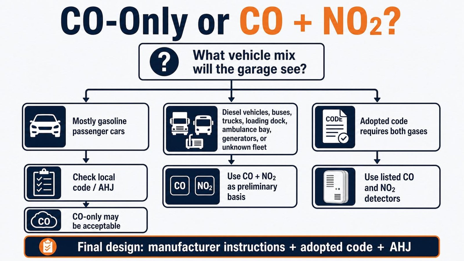
CO-only monitoring may still be accepted for a petrol/gasoline passenger-car garage, especially on older projects or in jurisdictions that have not adopted newer enclosed-garage language. Do not assume that is enough on every project.
Add NO2 monitoring when the garage regularly sees diesel vehicles, delivery trucks, buses, service vans, loading activity, ambulance bays, generators, or mixed-fleet operation. NO2 is also increasingly part of code-based enclosed parking garage control language, so check the adopted code edition and local amendments early.
Product and Decision Table
| Product | Best Fit | Gas / Range | Outputs and Controls | Watch Before Specifying |
|---|---|---|---|---|
| Macurco CM-6 / CM-12 | CO-only retrofit or small garage fan control | CO display range listed as 0-200 ppm; manufacturer lists coverage up to 7,500 sq ft | Fan relay, alarm relay, buzzer, 4-20 mA | CO-only device. If NO2 is required, use a separate NO2 device or a dual-gas option. |
| Macurco CX-6 / CX-12 | Dual CO/NO2 monitoring with local control | CO and NO2; replaceable sensors; CX-6 listed to UL 2075 per manufacturer | Display, buzzer, fan relay, alarm relay, 4-20 mA | Confirm low-voltage vs line-voltage model and exact listing requirements with the submittal. |
| Honeywell E3Point | Networked BAS projects and multi-gas flexibility | CO and NO2 among supported gases; Honeywell lists CO range 0-250 ppm and NO2 range 0-10 ppm in E3Point technical data | Standalone or network versions; relays; 4-20 mA or BACnet/Modbus depending on configuration | Confirm standalone, remote, or network model. Do not mix capabilities from different versions without checking the exact part number. |
| BAPI Digital CO/NO2 | Rough-service or duct applications with BAS communication | CO 0-500 ppm; NO2 0-20 ppm; approx. 7-year sensing elements per BAPI | Field-configurable BACnet MS/TP or Modbus RTU | Allow warm-up/commissioning time and confirm wall/beam vs duct configuration. |
| Conspec 911154-1 CO/VC | Purpose-built CO ventilation controller | CO 0-500 ppm; electrochemical sensor; listed sensor life expectancy 7 years | LCD, 80 dB alarm, fan relay, alarm relay, fail-safe fan operation on fault/power issue | CO-only. For diesel or code-driven NO2 requirements, pair with NO2 monitoring or use a dual-gas platform. |
| ACI CO-R | Budget-friendly analog CO input to BMS | CO 0-125 ppm default, 250 ppm max per ACI product page | 4-20 mA and 2-10 VDC output | No Modbus RTU compatibility per ACI. Best when the BMS provides the control logic. |
Sensor Coverage and Placement
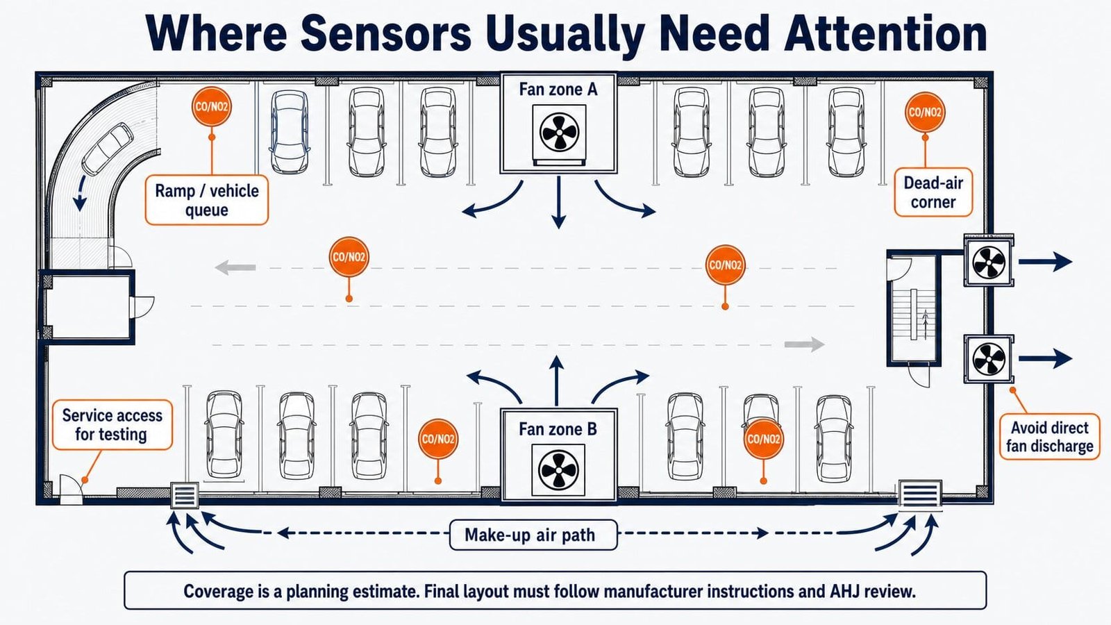
Do not write “one sensor per 5,000 sq ft” as if it is a universal code rule. It is only a rough budgeting number that can help during concept design. Manufacturer data may allow a different maximum coverage under listed conditions, and real garages have ramps, shafts, dead corners, jet fans, partitions, and traffic patterns that change the answer. For airflow-side coordination, BuildMEP’s duct sizing calculator can help with early ductwork checks.
- Start with manufacturer spacing and coverage instructions for the selected device.
- Add sensing where exhaust can collect: ramps, queuing lanes, payment areas, loading areas, low-airflow corners, and enclosed pockets.
- Zone sensors to match fan zones. A sensor on Level B2 should not always force every fan on every level to full speed.
- Mount in the occupied breathing zone unless the manufacturer or AHJ requires otherwise. Keep sensors away from direct tailpipe blasts, fan discharge, fresh-air openings, and washdown abuse.
- Coordinate access. A perfectly placed sensor that cannot be reached for bump testing and calibration will become a maintenance problem.
Preliminary Sensor Planning Tool
Use this only for early planning. It does not replace the manufacturer’s layout, mechanical code, fire/life-safety review, or the engineer’s final design.
Planning basis: area divided by 5,000 sq ft, adjusted for layout risk, with at least one sensor per level. Final count may be higher or lower after manufacturer layout and AHJ review.
Setpoints and BMS Control
Setpoints are where garage articles often get too confident. A value like 25 ppm CO can be a common first-stage fan trigger in some manufacturer defaults and project sequences, but it should not be presented as a universal legal requirement. NO2 trigger values are also project- and jurisdiction-dependent.
For a real project, confirm four things: the adopted code, the AHJ’s expected alarm levels, the sensor manufacturer’s allowable setpoint range, and the owner’s required sequence of operation.
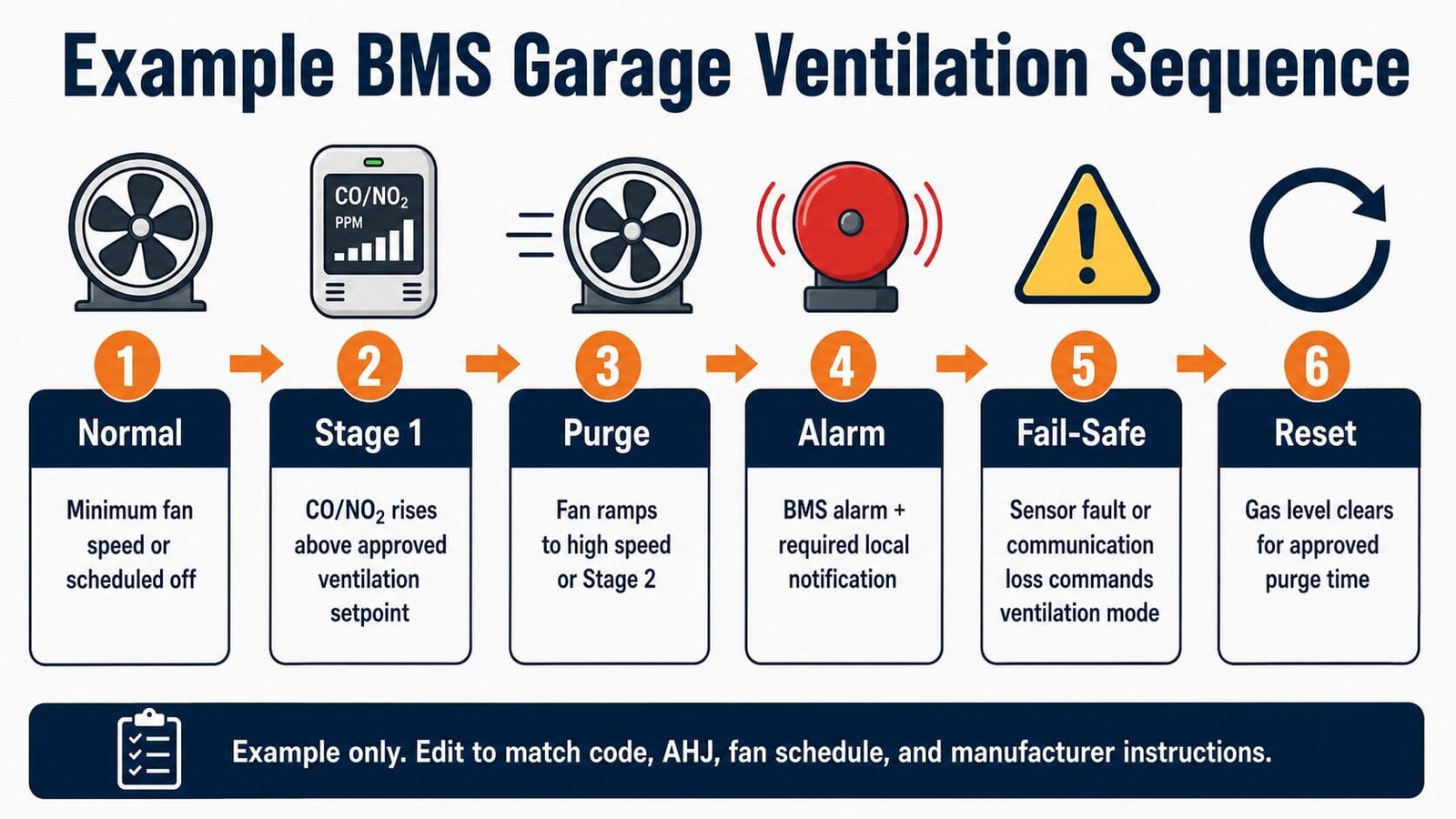
Example BMS Ventilation Sequence
This is an example only. Edit it to match the project code, AHJ comments, fan schedule, VFD minimum speed, smoke-control requirements, and manufacturer instructions.
- Under normal conditions, run garage exhaust fans at the scheduled minimum speed or off state allowed by the design.
- If any CO sensor in a zone rises above the approved Stage 1 setpoint for the approved delay period, enable that zone’s exhaust fan and associated make-up air path.
- If CO continues to rise, or if NO2 reaches its approved ventilation setpoint, increase the fan to Stage 2 or ramp the VFD to the scheduled high speed.
- If the high alarm level is reached, command the zone fans to high speed, generate a BMS alarm, and activate any required local alarm device.
- If a sensor reports fault, loss of communication, end-of-life, or power failure, place the affected zone in the fail-safe ventilation mode required by the design.
- After gas concentration falls below the reset threshold for the approved purge time, return the zone to normal scheduled operation.
- Trend CO, NO2, fan status, fan speed, alarms, sensor faults, and manual overrides for commissioning and maintenance review.
Maintenance Notes
- Label every sensor by level, zone, and BMS point name.
- Keep calibration records available for inspection and troubleshooting.
- Follow the manufacturer’s bump test, calibration, and sensor replacement instructions.
- Replace sensing elements before end-of-life alarms become nuisance calls.
- Test the full sequence, not only the sensor reading: sensor input, BMS alarm, fan start, VFD speed, damper response, and reset logic. For related control-signal thinking, see BuildMEP’s Siemens actuator replacement and BMS feedback guide.
Visual Guide
Bottom Line
For a simple CO-only retrofit, Macurco CM-6/CM-12 or ACI CO-R can be enough. For garages with diesel exposure, uncertain vehicle mix, or newer enclosed-garage code requirements, start with CO + NO2 and coordinate the exact model, coverage, and sequence with the AHJ. The best design is not the one with the fanciest sensor; it is the one that is clear to commission, easy to maintain, and honest about how the fans will respond when exhaust levels rise. For more practical HVAC references, browse the BuildMEP HVAC guides.