Part of Duct Design & Fabrication: The Complete BuildMEP Guide →
BuildMEP practical HVAC renovation guide
Pre-insulated ductwork can solve access, weight and sequencing headaches in a congested renovation—but only when the complete tested duct system, fabrication method and component interfaces actually suit the design duty. This guide turns that decision into a controlled field workflow.
Decision brief
Pre-insulated ductwork is a strong candidate for indoor comfort-air renovation where access is restricted, low installed weight matters, the insulation layer would otherwise be a pain to apply, and an approved system is available for the pressure, leakage, thermal, fire and cleaning requirements.
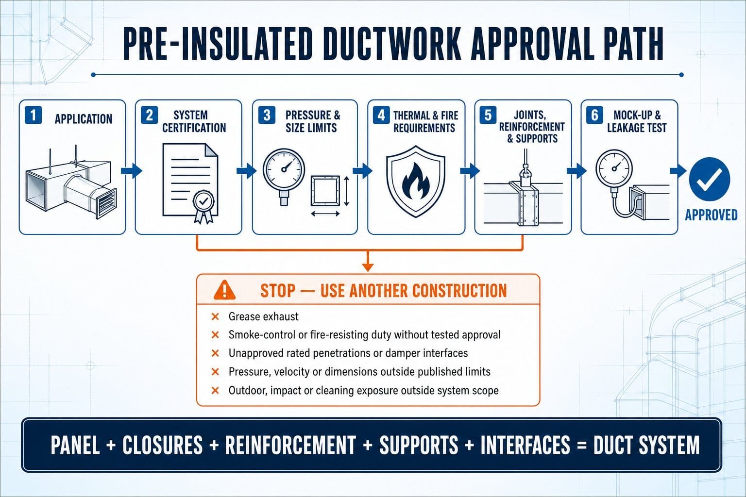
Don't select it from the panel description alone. The accepted construction is a whole system — panel, approved fabrication geometry, adhesives or sealants, closure tape, transverse joints, reinforcement, supports and equipment interfaces. Swap in an apparently similar accessory and you can invalidate the tested or published performance.
Stick with sheet metal—or another specifically tested construction— where the service demands fire resistance, smoke extract, grease exhaust, high mechanical-impact resistance, weather exposure, aggressive cleaning or a pressure/velocity duty outside the selected system's published limits.
What pre-insulated ductwork actually is
A typical rigid pre-insulated HVAC duct panel is an insulation core with facings on both sides. The internal facing forms the air-stream surface; the external facing protects the insulation and usually forms part of the vapour-control layer. The fabricated panel becomes the duct wall itself, so a separate external insulation wrap may not even be needed once the selected panel already meets the project's thermal resistance and vapour-control requirements.
The term covers more than one material and more than one certification route. Phenolic, polyisocyanurate (PIR), polyurethane (PUR/PU) and mineral-fibre ductboards can all have different properties, facings and approved construction details. Panel thickness, foil thickness and reaction-to-fire classification are product-specific. One current phenolic system, for instance, publishes 22 mm and 30 mm UK panels, while other regional product ranges run different sizes entirely. That's exactly why "20 mm is standard" isn't a safe universal spec.
Don't rank cores using a generic fire-behaviour table. Fire acceptance comes down to the tested finished product and the applicable classification—not some broad claim that one foam chars, drips or smokes less than another. In North American practice, rigid factory-made air ducts may be evaluated to UL 181; on the EN/BS side, insulation-ductboard performance is addressed by EN 13403, while reaction-to-fire evidence gets declared separately.
Use this when—and stop when—the application changes
Good renovation candidate
- Indoor comfort supply, return or extract air within the approved system scope
- Restricted delivery route or ceiling access
- Weight-sensitive support or handling conditions
- Need to combine duct wall and thermal insulation in one installation sequence
- Trained fabricator and complete manufacturer accessory system available
Do not assume suitability
- Grease, kitchen extract, smoke-control or fire-resisting duct service
- Rated barrier penetration without an accepted interface detail
- Outdoor exposure, washdown, impact-prone or corrosive areas
- Pressure, velocity, size or leakage duty outside published limits
- Hygiene or cleaning regime incompatible with the internal facing
"Lightweight" isn't an approval criterion on its own. One manufacturer comparison found a big reduction in installed mass for a specific phenolic duct, size, pressure and insulation duty, but that result doesn't automatically carry over to every PID/GI comparison. Calculate the actual panels, joints, reinforcement and supports for your project.
The submittal must prove a complete duct system
| Design input | Evidence to obtain | Decision it controls |
|---|---|---|
| Code and application | Adopted-code acceptance, certification/listing, intended-use statement and regional product identification | Whether the duct system is permitted in the occupancy, plenum and air service |
| Pressure and velocity | Positive/negative pressure limits, velocity limits, size tables and required reinforcement | Whether the duct will resist bulging, caving, joint load and service pressure |
| Leakage duty | Published leakage classification, closure system and project test method/pressure | Joint type, sealing workmanship and leakage-test scope |
| Thermal and condensation control | Declared conductivity, thickness, vapour-layer details and project condensation calculation | Panel selection and treatment of joints, damage and thermal bridges |
| Fire performance | Applicable finished-product classification, certification scope and code/AHJ acceptance | Where the duct may be installed; never infer fire resistance from surface classification |
| Cleaning and hygiene | Approved cleaning method, internal-surface durability and restrictions | Suitability for the occupancy and maintenance plan |
| Accessories and interfaces | Approved joints, adhesive, tape, sealant, reinforcement, supports, access doors and equipment/damper transitions | Whether the field-built duct preserves the system performance |
| Fabrication competence | Required training, approved fabricator status and current fabrication manual | Who is permitted to fabricate and label the system |
Pre-insulated duct vs insulated GI: compare the installed systems
| Project issue | Pre-insulated ductwork | Insulated galvanized-steel duct | Design implication |
|---|---|---|---|
| Access and handling | Potentially lighter; panels or shorter sections can be brought through restricted routes | Heavier finished assembly; factory sections may need larger access and lifting provision | Survey the delivery route and compare actual section weights |
| Installation sequence | Duct wall and insulation are integrated, subject to complete joint/vapour sealing | Metal installation and insulation are normally separate activities | PID may reduce overhead insulation work in a crowded void |
| Mechanical resistance | Facings and corners need protection from impact and trade damage | Generally more tolerant of knocks and local mechanical abuse | Consider construction traffic, access and future maintenance |
| Pressure, size and support | Controlled by the selected system tables and reinforcement method | Controlled by sheet-metal construction standard, gauge, reinforcement and pressure class | Compare against the same operating and test duty |
| Fire/life-safety interfaces | Requires an approved transition/detail at dampers and rated barriers | Familiar listed metal interfaces are widely available, but still detail-specific | Resolve dampers, sleeves, breakaway connections and access before selection |
| Modification and repair | Field changes must restore structure, airtightness and vapour-facing continuity | Metal can be altered with established fabrication methods, followed by insulation repair | Use approved repair details; do not patch damage cosmetically |
| Pressure loss | Use system-specific roughness and joint/fitting data where available | Use the applicable metal-duct and fitting data | Do not assume identical friction or fitting losses |
Before comparing construction materials, confirm airflow, velocity, available fan pressure and fitting losses. BuildMEP's duct size calculator is handy for preliminary geometry, while the static-pressure guide walks through the pressure budget the final duct route has to satisfy.
Renovation controls come before cutting panels
Existing false ceilings aren't empty workshops. They can hide live electrical services, sharp containment, fragile ceilings, concealed contamination, water-damaged materials and operating HVAC paths tied into occupied rooms. A lighter duct doesn't make any of that go away.
- Confirm the intrusive survey and hazardous-material assessment
- Approve the shutdown, isolation and lockout plan
- Survey the route, openings, lifting path and working clearances
- Coordinate live services and required temporary diversions
- Separate occupied areas from dust, debris and adhesive emissions
- Protect or isolate supply and return openings from contamination
- Review adhesive, sealant and cleaner safety data sheets
- Provide cutting-tool, blade, access and work-at-height controls
- Protect fire alarm, sprinklers and life-safety systems during the work
- Define daily cleaning, waste removal and area-release criteria
Tools, materials and prerequisites
Use the tooling specified for the selected panel system. A typical controlled setup might include:
| Group | Typical resources | Control point |
|---|---|---|
| Survey and setting out | Approved drawings/model, laser measure, tape, square, straightedge, marker and templates | Verify instrument condition and dimensions against site control |
| Panel fabrication | System-approved knives, groove/cutting tools, clean flat bench, clamping/holding aids and facing tools | Use the groove profile and allowances in the current fabrication manual |
| Closure system | Specified adhesive, sealant/mastic, vapour-barrier tape, joint profiles, corners and fasteners | Do not mix unapproved products; respect shelf life, temperature, cure and surface preparation |
| Structure and installation | Specified reinforcement, support channels, rods, load spreaders, edge protection and approved transitions | Select from size/pressure tables and protect panels from concentrated loads |
| QA and safety | PPE, SDS, calibrated test equipment, labels, inspection forms, lighting and housekeeping controls | Agree the mock-up, test pressure, acceptance criteria and records before fabrication |
A hot knife isn't a universal requirement. Use one only when the panel manufacturer permits it and the risk assessment covers fumes, heat and fire prevention. Same story with adhesive mixing: some products are single-component, while others come with defined mixing and pot-life requirements.
Controlled site-fabrication workflow
- Freeze the approved inputs. Record the drawing/model revision, duct service, airflow, dimensions, design pressure, leakage requirement, insulation duty and selected product system. Pull superseded fabrication schedules out of circulation.
- Survey the actual route. Verify the void, access openings, structure, existing services, equipment connections, dampers and maintenance clearances. Raise an RFI for conflicts instead of cutting around them informally.
- Plan sections and cutting yield. Decide which sections can pass through the access route and be safely supported. Nest pieces against the real panel dimensions, sequence larger parts first and identify reusable offcuts.
- Prepare the fabrication area. Store panels flat, dry and protected. Use a clean, level bench with enough space to support the full component without bending or damaging the facings.
- Set out from the system manual. Mark internal duct dimensions plus the exact groove, overlap, joint and facing allowances for the chosen construction method. Don't copy allowances from another brand or panel thickness.
- Cut and groove accurately. Make the approved straight, shiplap, V-groove or proprietary cuts while preserving the facing that acts as the fold hinge where required. The common double-bevel for a right-angle fold isn't a rule for every fitting.
- Dry-fold and check. Confirm internal dimensions, diagonals, squareness, joint closure and fitting geometry before adhesive goes on. Template complex transitions when site geometry is uncertain.
- Bond and close the duct. Prepare surfaces and apply the specified adhesive/sealant at the published coverage, temperature and cure conditions. Fold, align and hold the component without crushing the core.
- Complete the closure and vapour layer. Apply the approved tape, mastic or mechanical closure with the required overlap and pressure. Seal corners and penetrations. Tape should never be used to hide a poorly cut open joint.
- Add joints, reinforcement and accessories. Install only the transverse joint, flange, corner, fastener and reinforcement arrangement selected from the system's size and pressure tables.
- Install and support. Lift sections without loading corners or facings, use the specified support spacing and load-spreading method, and provide independent support at equipment, dampers and other concentrated loads where required.
- Inspect, test and record. Check dimensions, facing damage, closure continuity, reinforcement, support, access and component interfaces. Complete the project leakage test, repair by an approved method, update as-builts and release the system for cleaning/TAB.
For transitions, offsets and elbows, the airflow geometry still matters just as much. BuildMEP's guide to common HVAC design mistakes explains why sharp elbows, sudden transitions and unnecessary offsets drive up pressure loss; apply the selected PID manufacturer's cutting method to build the approved geometry.
Dampers, equipment and rated barriers need designed transitions
Dampers, coils, access doors, grilles, flexible connections and plant connections all bring weight, vibration, access needs and local loads that a plain panel wall may not be built to carry. Use the system's approved support and interface details and independently support heavy components where required.
A standard ventilation-duct fire classification is not a fire-resistance rating. Where a duct crosses a rated wall or connects to a fire or smoke damper, the damper listing, sleeve, breakaway connection, expansion clearance, access and penetration system all have to stay valid. Review BuildMEP's fire and smoke damper installation guide, then verify the exact damper and PID transition accepted for the project.
Flexible duct is a separate design choice—not a PID repair
Flexible duct can work well for final equipment or terminal connections where the adopted code, specification and listing permit it. It shouldn't get introduced automatically just because a rigid route is a hassle. First figure out whether the product is listed as a flexible air duct or an air connector; the latter may carry a labelled maximum installed length.
The Air Diffusion Council's sixth-edition guidance calls for the minimum length needed, fully extended installation, bends with a radius at least one duct diameter, supports at maximum 4 ft horizontal intervals, support material at least 1.5 in. wide and listed/labeled sealing methods. These are published North American industry requirements; the adopted code and manufacturer instructions still govern the project.
Compression, snaking and sharp bends all drive up pressure loss. A flexible section also needs continuity of its insulation and vapour barrier at the rigid connection. Treat it as a designed air-path component with a calculated pressure loss — not a convenient way to paper over a coordination problem.
Worked selection case: occupied-office retrofit
Given: An 8 m indoor supply branch serves four office diffusers. The approved internal duct size is 600 × 300 mm, airflow is 1.0 m³/s and the design positive pressure at the branch is 400 Pa. The route runs above an occupied office with a restricted access opening. It crosses one rated partition at an existing fire damper. The duct isn't grease exhaust, smoke extract or outdoor service.
Preliminary airflow check: The duct area is 0.18 m², giving an average velocity of roughly 5.6 m/s. That doesn't select the construction on its own, but it feeds into pressure-loss, acoustic and product-limit checks.
- Application screen: Indoor comfort supply air sits within the normal application family for an approved phenolic duct system. Restricted access and handling favour a lighter, sectional construction.
- Performance screen: The engineer checks the selected system's published positive pressure, velocity, duct-size, leakage and reinforcement tables against 400 Pa service pressure and the specified test duty. No value gets inferred from panel thickness alone.
- Thermal screen: The declared conductivity and thickness are checked against the project insulation and condensation calculation, including joint and support thermal bridges.
- Fire-interface screen: PID is used only on the comfort-air branch. The existing damper, sleeve and rated penetration stay governed by their listed detail; the PID-to-metal transition gets submitted before fabrication.
- Renovation screen: The ceiling is surveyed, the work zone is isolated from occupied areas, the AHU branch is shut down, and fabrication is assigned to a clean site workshop rather than the ceiling void.
- Pressure-loss screen: The route is recalculated with the applicable duct/joint and fitting data. The existing fan duty is checked; PID isn't assumed to share the same roughness or fitting loss as galvanized steel.
- QA release: A representative joint and damper transition are approved as a mock-up. Installed ductwork is inspected and leakage-tested at the project-specified pressure before ceiling closure and TAB.
Decision: PID is suitable for this branch only once the selected system clears all six screens and the damper transition is accepted. If the pressure/reinforcement data or rated-wall interface can't be demonstrated, insulated GI stays the safer pick despite the access disadvantage.
Example values are engineering assumptions for illustrating the workflow, not universal selection limits.
Failure modes that look acceptable at first
| Mistake or cause | Consequence | Field symptom | Correction |
|---|---|---|---|
| Panel approved without the complete system | Closures, joints or reinforcement do not match tested performance | Mixed tapes, adhesives and flange profiles on site | Reconcile every accessory with the approved submittal and manual |
| Generic reinforcement threshold used | Panel bulging, caving or joint load beyond design | Wall movement or seam distress during fan operation/test | Select reinforcement from the exact size, pressure and joint table |
| Tape applied over an open or contaminated seam | Air leakage and vapour-barrier failure | Loose tape, dirt track, condensation or failed leakage test | Reopen and rebuild the joint with approved preparation and closure |
| Facing punctured or crushed during lifting | Local structural and vapour-control damage | Torn foil, exposed core or dented corners | Assess and repair using the approved detail—or replace the section |
| Heavy component carried by the panel | Concentrated load distorts the duct or joint | Sag around damper, access door or equipment connection | Provide the required independent support and approved interface |
| Site dimensions copied from an obsolete drawing | Forced offsets, poor fitting geometry and blocked access | Field-cut patches and last-minute flexible-duct additions | Survey, coordinate and reissue the fabrication schedule |
| Occupied-area controls omitted | Dust, odour or debris reaches occupants/HVAC system | Complaints, contaminated grilles or visible migration | Stop, isolate, clean and reinstate the approved IEQ controls |
| Material changed without recalculating the route | Fan pressure or terminal airflow no longer meets design | TAB shortfall or excessive balancing-damper closure | Recalculate pressure loss and verify fan/TAB duty |
Inspection and handover checklist
- Confirm panel and accessory identification against the submittal
- Confirm fabricator qualification where required
- Measure duct dimensions and fitting geometry
- Inspect internal and external facings for damage
- Inspect seams, tape overlap, corners and vapour continuity
- Compare joints and reinforcement with the approved table
- Verify support spacing and load distribution
- Verify independent support for components and transitions
- Verify access doors and maintainable clearances
- Confirm damper and rated-barrier interfaces
- Witness the specified duct leakage test
- Record repairs and retest affected sections
- Remove fabrication debris and clean by an approved method
- Update as-built drawings and inspection records
- Release the system for TAB and ceiling closure
Frequently asked questions
Does pre-insulated ductwork always eliminate external insulation?
No extra wrap is normally needed only when the approved panel thickness, conductivity, joints and vapour-control details actually satisfy the project's thermal and condensation requirements. A product name alone doesn't prove that.
Is phenolic always better than PIR or PU?
No. Compare the finished duct system's certification, thermal performance, pressure/size limits, closures, mechanical durability, cleaning method and local acceptance. Don't pick from a generic core-material fire ranking.
Can PID be fabricated directly inside the ceiling void?
Final trimming or fit-up may be allowed by the project procedure, but primary fabrication should happen in a clean, flat and controlled work area. Overhead cutting and adhesive work push up quality, contamination and safety risks all at once.
Can the same aluminum tape be used on every panel system?
No. Use the closure product and preparation method specified or listed for the selected system. UL 181A, for example, evaluates closure systems for rigid air ducts; an aluminum appearance doesn't establish equivalence.
Is PID limited to low-pressure ductwork?
Don't assign a generic pressure category. Published limits vary by system, duct size, joint and reinforcement. SMACNA's first-edition phenolic standard sets out construction provisions within its stated scope, while individual products may publish different leakage or pressure capabilities.
Can flexible duct solve every congested-ceiling conflict?
No. Flexible duct adds pressure loss and comes with routing, support, length and listing constraints. Use it only where the design and adopted requirements permit it, at the minimum practical length and without compression or sharp bends.
Evidence trail and limitations
- ASHRAE Handbook—HVAC Systems and Equipment, 2024, Chapter 19—phenolic duct system definition, panel construction, joint-system context and UL 181 Class 1 reference.
- UL Solutions: Air Ducts and UL 181—fire, material and integrity test categories; UL 181A/181B closure-system context.
- SMACNA Products & Services Guide, 2025—scope and content of ANSI/SMACNA 022-2015 Phenolic Duct Construction Standards.
- BSI: BS EN 13403:2003—current insulation-ductboard standard scope, performance characteristics and test topics.
- Kingspan KoolDuct technical information—a product-specific example of phenolic core, facings, dimensions, declared fire classification and leakage performance. It is not a universal PID specification.
- Air Diffusion Council, Flexible Duct Performance & Installation Standards, 6th Edition—air duct/air connector identification, routing, extension, bend, support and sealing guidance.
- NIOSH Publication 2020-110—planning, isolation, dust/contaminant control and occupied-building indoor-environmental-quality guidance during renovation.
Certification and product data vary by country and product family. Confirm the supplied label, current manual and project-adopted standard rather than relying on a global product-page statement.
Part of a BuildMEP guide
This article is one step in Duct Design & Fabrication: The Complete BuildMEP Guide. It puts static pressure, fitting geometry and on-site fabrication in the order you actually deal with them on a project.