Part of Duct Design & Fabrication: The Complete BuildMEP Guide →
BuildMEP practical HVAC fabrication guide
Use this guide to check rectangular-duct elbows, transitions and offsets before fabrication starts. It walks through what to measure, how to calculate the required transition length, and where the project specification or fitting-loss data has to make the final call rather than habit.
Decision brief
Don’t approve a duct fitting off a remembered angle or radius ratio alone. First confirm how the drawing defines the radius, which duct dimension sits in the plane of the turn, whether vanes are part of the specified fitting, and whether the stated angle is measured from the duct axis or as an included angle.
The geometry check only answers whether the fitting matches the drawing or project criterion. The pressure-loss check is a separate step: pull the applicable loss coefficient for the actual fitting geometry and calculate its loss at the design velocity.
Field reality: the fitting is often decided before the calculation
A technician often has to start an elbow or offset from whatever space is left once other services are installed. By the time a reviewer spots a throat that’s too tight or a transition that’s too short, the sheet metal is already cut. A useful check has to sit on the coordinated shop drawing and at the fabrication hold point—not just buried in the final static-pressure calculation.
The fix isn’t “make everything 1.5R” or “use 15 degrees everywhere.” It’s to identify the fitting type, apply the project-defined geometry, and then verify the associated pressure loss against recognized fitting data.
Three different Duct Fitting Geometry
Elbow
Changes the airflow direction. Check the radius convention, the width in the plane of turn, the vane arrangement and the fitting-loss coefficient.
Transition
Changes the duct size or shape. Check the lateral change on each moving face, the available axial length and the resulting side angle.
Offset
Shifts the duct centerline while usually keeping the same size. Check the offset distance, bend angle, run length, fitting form and clearance.
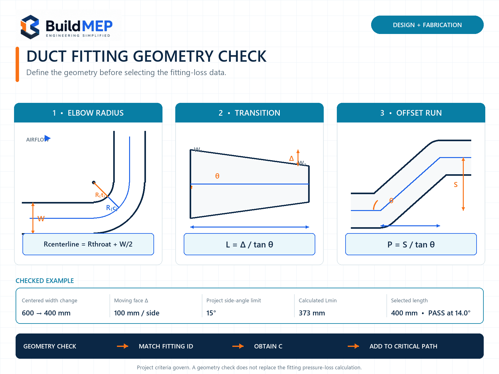
Elbow radius: define R and W before using R/W
For a rectangular elbow, W is the duct dimension in the plane of the turn, so a horizontal turn can end up with a different W than a vertical turn on the very same rectangular duct. The symbol R isn’t universal, either: one drawing might dimension the centerline radius, while another shows the inside or throat radius.
You can’t check a ratio safely until you know that convention. If the criterion is Rcenterline/W ≥ 1.0 for a 600 mm-wide turn, the centerline radius needs to be at least 600 mm, which puts the throat radius at 300 mm. If the drawing’s R dimension is actually the throat radius, the same number means something completely different.
Do not turn a common detail into a universal SMACNA minimum
SMACNA publishes construction and duct-design references, but it’s the project specification that usually picks the actual elbow geometry. The U.S. Department of Veterans Affairs detail referenced below, for instance, shows a standard/long-radius arrangement with R at least W, plus short-radius alternatives with vanes. That’s a published owner detail—not proof every project uses the same radius definition or acceptance limit.
| Condition | What to verify | Why it matters | Disposition |
|---|---|---|---|
| Radius elbow | R convention, W in plane of turn, straight tangents and available clearance | Radius ratio changes the fitting loss and physical envelope | Accept only against the project detail and matching loss data |
| Short-radius elbow | Required splitter vane arrangement, support and orientation | A short radius without the specified vanes is a different fitting | Return for redesign or explicit engineer approval |
| Mitered elbow | Turning-vane type, spacing, leading-edge direction and access | Vanes are part of the aerodynamic geometry, not an optional accessory | Inspect before closing the duct |
| Changing-size elbow | Inlet/outlet areas, aspect ratios and the correct database fitting | It can’t be evaluated as a constant-area elbow | Use matching fitting data rather than a generic coefficient |
Transition angle: calculate it from the moving face
A transition-side angle is normally measured between a moving duct face and the straight duct axis. If a specification caps that angle at θmax, the minimum axial length works out to:
Here, Δ is the lateral movement of the face you’re checking. In a centered transition, that change splits across two opposite faces. In a flat-on-top, flat-on-bottom or one-sided transition, the moving face can end up taking the full dimensional change on its own.
- Centered width change: ΔW = |W1 − W2| / 2
- One-sided width change: ΔW = |W1 − W2|
- Centered height change: ΔH = |H1 − H2| / 2
- Required length: take the larger result across every moving face
For a symmetric transition with both opposite faces at 15°, the included angle comes out to 30°. That shorthand breaks down for an asymmetric transition with one face held flat.
The 15° value is a specification choice, not a universal law
NASA’s UFGS 23 31 13.00 40 includes editor-selectable text capping a transition side at 15° from the straight run, with separate upstream/downstream equipment-transition options. The brackets matter—a project specifier still has to select and adopt that value. Work from the issued project specification first, then the applicable design reference and fitting-loss data.
Converging and diverging transitions are not interchangeable
A converging transition speeds the flow up; a diverging transition slows it down and is generally far more sensitive to boundary-layer separation and poor pressure recovery. None of that justifies inventing a universal second angle, though. Select the actual converging or diverging fitting in the ASHRAE or SMACNA loss data, and check the area ratio, aspect ratio and length or angle that fitting definition actually uses.
Offset geometry: treat it as two direction changes
An offset usually keeps the same duct cross-section while shifting the centerline, so it’s not just a reducer turned sideways. For a simplified equal-angle offset with centerline shift S and diagonal centerline angle θ:
Diagonal centerline length D = S / sin θ
These equations only establish the layout envelope. The fabricated length still has to allow for the selected bend form, tangent points, seams, reinforcement and connection clearances. Pressure loss needs to come from the matching offset or elbow arrangement, too—two closely spaced direction changes can interact, so don’t automatically treat them as two isolated fittings.
Worked geometry check
Given: a centered transition from 600 × 400 mm to 400 × 300 mm. The issued project specification caps each moving face at 15° from the duct axis. A separate same-size offset needs to shift the centerline by 300 mm using 30° direction changes.
1. Width-face requirement
ΔW = (600 − 400) / 2 = 100 mm per side
LW = 100 / tan 15° = 373 mm
2. Height-face requirement
ΔH = (400 − 300) / 2 = 50 mm per side
LH = 50 / tan 15° = 187 mm
3. Select and check the transition length
The width change governs, so the axial length needs to be at least 373 mm. Rounding to a practical selected length of 400 mm:
- Width-face angle = tan−1(100/400) = 14.0°
- Height-face angle = tan−1(50/400) = 7.1°
4. Lay out the offset envelope
P = 300 / tan 30° = 520 mm axial run
D = 300 / sin 30° = 600 mm diagonal centerline length
The offset result is simplified centerline geometry, nothing more. Add the actual fitting tangents and joint allowances shown on the approved fabrication detail.
5. Complete the pressure check
Select C for the actual elbow, transition or offset from the applicable ASHRAE Duct Fitting Database or the project-approved SMACNA design data. Don’t borrow a coefficient from a different radius, area ratio, aspect ratio, vane arrangement or flow direction.
Fabrication review workflow
- Mark the airflow direction and work out whether the fitting is an elbow, transition, offset or combination fitting.
- Confirm every geometric definition: centerline or throat radius, moving face, side angle, included angle and plane-of-turn width.
- Read the issued project detail and specification before falling back on a remembered value.
- Calculate the physical envelope and compare it with the coordinated ceiling or plantroom space.
- Identify vanes and reinforcement as part of the fitting, including orientation and support.
- Match the fitting to loss data and add its loss to the critical duct path.
- Hold fabrication where geometry is unresolved—don’t let a coordination shortage quietly change the fitting type.
- Record the approved deviation when the designer accepts a different fitting and fan/static-pressure impact.
Failure-mode register
| Mistake | Consequence | Field symptom | Correction |
|---|---|---|---|
| Using centerline R/W against a throat-radius dimension | The accepted elbow is not the geometry the calculation assumed | Shop drawing appears compliant but the fabricated throat is unexpectedly tight | Show both radii or state the radius convention explicitly |
| Substituting a mitered elbow without the specified vanes | Different pressure loss and flow distribution | High local noise, poor downstream distribution or excess measured loss | Restore the specified fitting or obtain a checked redesign |
| Reading 15° per side as a universal 30° rule | An asymmetric transition may be too short | One moving face is visibly steeper than the criterion | Calculate each moving face separately |
| Checking only the width change | The height face can exceed the limit | Transition fits in plan but not in elevation | Use the governing length from width and height |
| Treating an offset as a reducer | Direction-change losses and tangent requirements are missed | Compressed Z-offset with insufficient straight separation | Lay out the centerline and use matching offset/elbow data |
| Approving geometry without a loss coefficient | Fan static-pressure budget remains incomplete | Design airflow is not achieved even though straight duct is correctly sized | Add every selected fitting to the critical-path pressure calculation |
Design and site verification handoff
- Confirm the adopted project specification, standard edition and authority requirements.
- Confirm the elbow radius convention and W dimension on every relevant detail.
- Measure each moving transition face and calculate its actual angle.
- Compare offset run, diagonal length and fitting tangents with coordinated clearance.
- Verify vane type, spacing, direction, supports and access before closing the duct.
- Record the fitting identifier, coefficient basis, velocity pressure and calculated loss.
- Add the loss to the critical duct path and compare it with the selected fan duty.
- Photograph and sign off concealed fittings before insulation or ceiling closure.
Focused questions
Is R/W = 1.5 always required?
No. It’s a commonly selected design geometry, but the controlling requirement is always the issued project detail or specification, plus the pressure-loss calculation for the actual fitting. Always confirm whether R means centerline or throat radius.
Does “15° transition” mean 15° included angle?
Not necessarily. Most specifications express the angle of each moving face from the straight duct axis. A centered transition with two faces at 15° works out to a 30° included angle—an asymmetric transition with one face flat doesn’t.
Can turning vanes make any square elbow acceptable?
No. The vane type, spacing, orientation, support and elbow proportions all have to match the specified or tested fitting. Bolting in improvised vanes doesn’t give you a valid loss coefficient.
Can this geometry check replace a static-pressure calculation?
No. Geometry only tells you which fitting data apply. The system calculation still needs the fitting loss coefficient, the velocity pressure and the complete critical path.
Evidence trail and limits
- SMACNA Technical Standards — identifies HVAC Duct Construction Standards—Metal and Flexible, 4th Edition (2020) as the current flagship construction reference. Confirm the project-specified edition and use that one.
- ASHRAE Duct Fitting Database — provides geometry-dependent loss coefficients and pressure-loss calculations covering more than 200 round, rectangular and flat-oval fittings.
- 2021 ASHRAE Handbook—Fundamentals, Chapter 21: Duct Design — describes the fitting-loss method and how the database fitting identifiers get used.
- U.S. Department of Veterans Affairs, Ductwork Radius Elbows, detail SD233100-02 (December 2008) — an owner-detail example that draws the line between standard-radius and short-radius/vane arrangements.
- NASA UFGS 23 31 13.00 40, Metal Ducts — contains editor-selectable radius, vane and transition-angle clauses. The bracketed values only become requirements once someone selects them in the issued project specification.
This guide is a design and fabrication review aid—it doesn’t replace the contract documents, a licensed designer’s approval, or the complete ASHRAE/SMACNA fitting-loss data. Updated 26 August 2026.
Continue the duct-design check
Part of a BuildMEP guide
This article is one step in Duct Design & Fabrication: The Complete BuildMEP Guide. It puts static pressure, fitting geometry and on-site fabrication in the order you actually deal with them on a project.