Part of Fire Protection Systems: The Complete BuildMEP Guide →
Independent fire-protection design guide
Use this guide to translate a hydraulic demand into a defensible fire-pump duty, then check the selected pump at churn, rated flow and 150% of rated flow.
Decision brief: size from the system demand and the actual certified curve
Do not size a fire pump from one percentage rule. Establish the required flow and pressure from the approved hydraulic calculation, account for the available suction condition, and select a listed pump whose certified curve satisfies the demand without creating an unacceptable churn pressure.
The familiar values—140% at churn and 65% at 150% flow—define performance boundaries for a listed centrifugal fire pump. They are not the pressure values that every pump will produce, and they do not replace a model-specific curve.
What the three curve points actually mean
A centrifugal fire pump is not selected at the nameplate point alone. The certified shop curve and the field acceptance test should be read as a continuous relationship between flow and net pump pressure.
| Curve point | Performance boundary | What the designer checks |
|---|---|---|
| Churn / shutoff | Zero flow; shutoff head does not exceed 140% of rated head. | Maximum system pressure, component ratings, pressure-relief or pressure-regulating strategy, and controller setpoints. |
| Rated point | 100% rated flow at 100% rated net pressure. | The pump nameplate duty and the reference point for the listed curve. |
| Overload point | At 150% of rated flow, net pressure is not less than 65% of rated pressure. | Whether the pump, driver and suction supply remain acceptable at the high-flow test condition. |
These are limits, not a substitute curve. A specific pump may shut off well below 140% and may deliver substantially more than 65% pressure at 150% flow. Procurement and review must therefore use the manufacturer’s certified curve for the exact pump, speed and impeller.
Fire-pump sizing workflow
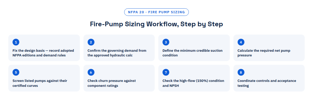
- Fix the design basis. Record the adopted NFPA editions, hazard or standpipe criteria, simultaneous demand rules, water-supply test date and AHJ conditions. Do not mix values from different editions without documenting the reason.
- Confirm the governing demand. Use the approved hydraulic calculation to identify the controlling flow and required residual pressure. For a combined system, verify which sprinkler, standpipe and hose-stream demands must operate simultaneously.
- Define the minimum suction condition. Use the credible minimum supply pressure at the required flow, not a static gauge reading. Account for tank level, suction-pipe friction, backflow devices, strainers and any permitted minimum municipal-main condition.
- Calculate the required net pump pressure. Add the required discharge-side pressure and losses, then subtract the available suction pressure at the same flow.
- Screen listed pump ratings. Choose candidate listed pumps, then plot the governing demand on each certified curve. The curve—not a shortcut percentage—must show adequate net pressure at that flow.
- Check churn pressure. Combine the pump’s actual shutoff pressure with the maximum credible suction pressure. Compare the resulting discharge pressure with the ratings of pipe, fittings, valves, sprinklers, hose valves and other components.
- Check the high-flow condition. Review the actual 150% point, driver loading and suction condition. Where the installation requires nonnegative suction pressure at the pump flange, verify it using the applicable NFPA 20 condition; tank and open-source installations also require the relevant submergence and net positive suction head checks.
- Coordinate controls and acceptance testing. Set the pressure-maintenance pump and fire-pump start sequence from calculated system pressures. Confirm that the test header or flow meter can demonstrate the required acceptance points without exceeding the available water supply.
Worked selection check
Example: compare two candidate pumps using their curves
Assumed project inputs for illustration:
- Governing system demand: 1,350 gpm.
- Required pressure at the system connection: 92 psi.
- Loss from pump discharge flange to that connection: 8 psi.
- Minimum available suction pressure at 1,350 gpm: 18 psi.
Candidate A: 1,000 gpm at 90 psi. Its certified curve shows 78 psi at 1,350 gpm. It fails the 82 psi requirement even though 1,350 gpm is below 150% of its rated flow.
Candidate B: 1,250 gpm at 90 psi. Its certified curve shows 86 psi at 1,350 gpm. It passes the demand point with 4 psi of curve margin.
The next checks are not optional: confirm Candidate B’s shutoff pressure against the maximum suction condition and system pressure ratings; confirm its 1,875 gpm point is at least 58.5 psi net; check the driver power across the required curve; and verify that the water supply and suction arrangement support the applicable high-flow test.
Selection result: Candidate B is the better of these two assumed pumps. The exercise does not approve a real product; final selection requires the exact certified curve, listed assembly data and project/AHJ review.
Why the “80% pump sizing rule” is unsafe
A rule that chooses rated pump flow as 80% of system demand can accidentally produce a workable candidate because the demand then falls at 125% of rated flow. But it proves neither pressure nor suction adequacy. Two pumps with the same rated flow and pressure can have different curve shapes and shutoff pressures.
Use percentages to understand the curve and test points—not to skip the hydraulic duty. The defensible record is the demand point plotted on the selected pump’s certified curve, supported by the suction calculation and pressure-rating check.
Jockey pump: separate leakage control from fire demand
The pressure-maintenance, or jockey, pump replaces small leakage and prevents nuisance starts of the main fire pump. The frequently repeated “1% of main-pump flow” value is a preliminary rule of thumb, not a universal NFPA 20 sizing answer.
Confirm that the selected jockey pump can restore normal leakage within the project’s control strategy but cannot satisfy a meaningful fire-protection demand that should start the main pump. Review its shutoff pressure, system pressure rating, start/stop differential, expansion provisions and likely cycling frequency as one coordinated package.
Failure-mode register
| Mistake | Consequence | What reveals it | Correction |
|---|---|---|---|
| Assuming every pump produces exactly 140% at churn and 65% at 150% flow. | Incorrect maximum-pressure and demand calculations. | Certified curve differs from the assumed straight-line curve. | Use the exact listed pump curve at the selected speed and impeller. |
| Selecting rated flow from the “80% rule” alone. | The pump can miss the required pressure at system demand. | Demand point plots below the certified curve. | Calculate net pressure and plot the governing demand point. |
| Using static water pressure as suction pressure. | Available pressure is overstated during flow. | Hydrant or tank-supply data show a lower residual condition. | Model the minimum credible residual supply at the same flow. |
| Checking only the demand point. | Excess churn pressure or inadequate high-flow performance is missed. | Component ratings or the 150% test condition fail. | Review churn, rated, demand and 150% points together. |
| Sizing the jockey pump only as a percentage of main-pump flow. | Nuisance cycling, failure to maintain pressure, or delayed main-pump start. | Frequent starts, long recovery or unstable setpoint sequence. | Base capacity on leakage and coordinate the complete pressure sequence. |
Design and submittal checklist
- Confirm the adopted NFPA 20 edition and all applicable system-design standards.
- Record the governing flow and pressure from the approved hydraulic calculation.
- Document minimum and maximum suction conditions and the water-test basis.
- Plot the governing demand on the exact certified pump curve.
- Compare maximum discharge pressure at churn with every affected component rating.
- Verify 150% flow performance, suction pressure or source limitations, and driver loading.
- Coordinate jockey-pump duty and controller pressure setpoints.
- Confirm test-header or flow-meter capacity and safe water discharge.
- Submit the listed pump, driver and controller data as a matched assembly.
- Obtain AHJ acceptance before purchase where the design depends on a special condition or local interpretation.
Continue the BuildMEP fire-protection workflow
- Use the complete BuildMEP fire-protection guide to place the pump decision within the wider suppression, hydrant and passive-protection workflow.
- Coordinate downstream installation activities with the fire sprinkler installation, testing and commissioning method statement.
- Before submitting the selected pump package, check the certificates, drawings and compliance evidence using the submittal checklist and compliance-matrix template.
Editable document
Turn the selection into an installation and commissioning plan
Once the pump duty is established, the Fire Pump Method Statement ($7) provides an editable installation, testing and commissioning framework for electric duty, diesel standby and jockey-pump arrangements, including pre-commissioning checks, test records and an inspection and test plan.
Get the Method Statement →Frequently asked questions
Can system demand exceed the pump’s rated flow?
A listed centrifugal fire pump is evaluated beyond its rated point, including at 150% of rated flow. That does not mean every demand below 150% automatically works. The certified curve must still provide the required net pressure, and the supply, driver and installation must satisfy the applicable requirements.
Is a larger fire pump always safer?
No. A larger pump can create excessive churn pressure, complicate pressure control and poorly match the operating range. Select from the hydraulic demand and actual curve, then check both minimum and maximum pressure conditions.
Is jockey-pump flow always 1% of main-pump flow?
No. Treat 1% only as an early estimate. Final capacity should reflect expected leakage and the required pressure-control sequence without masking a fire demand that must start the main pump.
Does the 150% point mean the system should be designed to operate there?
Not automatically. It is a required pump-performance and test reference. The project demand should be plotted and reviewed on the actual pump curve, with the accepted design range confirmed for the adopted edition and AHJ.
Primary references
- National Fire Protection Association, NFPA 20, Standard for the Installation of Stationary Pumps for Fire Protection, 2025 edition—pump installation, listed performance and acceptance-test framework.
- NFPA Fire Pumps Technical Committee, committee material illustrating NFPA 20 centrifugal-pump curve limits—140% maximum shutoff head and 65% minimum head at 150% rated flow.
- National Fire Protection Association, NFPA 25, Standard for the Inspection, Testing, and Maintenance of Water-Based Fire Protection Systems, 2023 edition—in-service fire-pump testing context. Confirm the edition adopted for the property.