BuildMEP commercial kitchen ventilation guide
A commercial kitchen ecology unit—more formally a pollution control unit (PCU)—can reduce grease aerosol, smoke particulate and odour before exhaust reaches a sensitive discharge location. This guide turns the unit into a coordinated design decision rather than a filter box added after the duct route is fixed.
Technical review: 14 September 2026 | Scope: Ducted Type I commercial kitchen exhaust; verify the adopted code and authority requirements for the project location.
Decision brief
Do not specify an ecology unit from airflow or duct size alone. Define the cooking duty and emission problem first, then select a listed treatment assembly that meets the required particulate and odour performance at the design airflow.
The approval needs to close seven linked checks:
- cooking appliances and grease/smoke/odour loading;
- discharge location and nearby receptors;
- required treatment stages and independently supported performance;
- rated airflow, pressure loss and exhaust-fan duty;
- listing, fire suppression, interlocks and adopted-code requirements;
- service withdrawal space, wash-down drainage and structural support; and
- commissioning measurements plus a maintainable cleaning/replacement plan.
What an ecology unit actually is
“Ecology unit” is a common project and supplier term. Codes and certification bodies may call the same class of equipment a pollution control unit. UL describes a PCU as an assembly installed in line with a commercial grease duct carrying heat, smoke and grease-laden vapours to the outdoors.
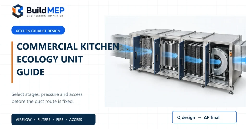
The housing can contain several modules: grease prefiltration or impingement, an electrostatic precipitator (ESP), mechanical after-filters, ultraviolet treatment, adsorbent media, wash systems, fire protection, controls and sometimes the exhaust fan. The exact sequence is manufacturer-specific.
Schematic only. Follow the selected manufacturer’s listed arrangement; not every system uses every stage or places the fan in the same cabinet.
Treatment stages: what each one can prove
| Stage | Primary job | What it does not prove | Submittal check |
|---|---|---|---|
| Hood grease filter or extractor | Captures grease near the source and protects the grease duct and downstream equipment. | It does not by itself control fine smoke or gaseous odour at the final discharge. | Hood listing, appliance duty, filter type, capture-and-containment test and cleaning access. |
| Prefilter, mesh or impinger | Intercepts larger droplets and debris, distributes airflow and reduces loading on the next stage. | “Prefilter included” does not state final particulate or odour performance. | Media type, pressure drop, wash/replacement method, drain path and required upstream/downstream screens. |
| Electrostatic precipitator | Charges fine grease and smoke particles and collects them on oppositely charged or grounded plates. | ESP particulate capture is not the same as odour removal. Capacity and efficiency depend on configuration, test basis, airflow and maintenance condition. | Rated airflow at the specified target efficiency, test method, number of passes, cell status monitoring, wash arrangement and pressure loss. |
| UV treatment | In a specifically designed system, UV can be used as part of grease-vapour and odour treatment. | A generic UV-C lamp is not proof of emission performance. ASHRAE has noted the historic lack of consistent measurements and test methods for UVC effectiveness on cooking effluent. | Manufacturer test basis, lamp wavelength/output, shielding, access interlock, airflow interlock, lamp-life monitoring, ozone strategy and replacement procedure. |
| Activated carbon or other adsorbent | Adsorbs selected gaseous and vapour-phase odour compounds on porous media. | Carbon does not replace particulate control, and visual cleanliness does not prove remaining adsorption capacity. | Media type and mass, contact-time basis, inlet conditions, pressure loss, change-out criterion and safe disposal method. |
| Final mechanical filter / HEPA | Provides a defined downstream particulate stage where the listed product or project performance requires it. | HEPA is not a universal ecology-unit requirement and can add substantial final resistance. | Filter classification/test standard, initial and final pressure drop, sealing, monitoring and replacement access. |
A better shorthand than “ESP removes smoke; carbon removes smell”
Use the shorthand only as a first explanation. In reality, cooking emissions contain droplets, solid particles and gas-phase compounds across a wide size and chemistry range. The ESP primarily addresses charged particles and aerosols; adsorbent media addresses compatible gas- and vapour-phase compounds. Neither statement establishes a guaranteed result at the property boundary without a defined duty, performance basis and maintained system.
Select the treatment train from the kitchen duty
Start with the appliance schedule, cooking process and operating hours. A bakery oven, light-duty reheating line, deep-fat fryer, wok range, charbroiler and solid-fuel appliance do not impose the same grease, smoke or odour load.
| Condition | Design implication | Evidence to obtain |
|---|---|---|
| Low grease/smoke duty with a compliant high-level termination and no sensitive receptor | A separate PCU may not be required; do not add one without a defined performance need. | Appliance duty, capture-and-containment design, discharge assessment and AHJ decision. |
| Grease and visible smoke near façades, terraces or outdoor-air intakes | Particulate treatment may need multiple stages and verified efficiency at the design flow. | Cooking-emission basis, receptor plan, target particulate performance and product test data. |
| Odour-sensitive mixed-use or residential adjacency | Particulate control alone is unlikely to resolve the full complaint; assess adsorbent or other approved odour treatment and discharge dispersion. | Odour-risk assessment, media selection/contact basis, replacement plan and authority conditions. |
| Heavy grease loading and long operating hours | Service interval, wash system, drain capacity and maintenance access become selection criteria, not afterthoughts. | Loading classification, wash cycle, detergent/water demand, wastewater route and staff/service contract. |
| Solid-fuel or extra-heavy-duty cooking | Use only a PCU specifically designed and listed for that application; generic kitchen filtration is not enough. | Product listing, temperature/fire provisions, spark/ember strategy and adopted-code approval. |
Airflow, filter area and fan pressure
1. Freeze the hood exhaust airflow
Take the design airflow from the coordinated hood schedule and approved commercial-kitchen ventilation design. The PCU is selected to pass that airflow while the hood still captures and contains the cooking plume. ASHRAE Standard 154-2022 provides design criteria for commercial cooking ventilation systems; the adopted local code and hood listing remain controlling.
2. Select at the required treatment performance
Manufacturer tables may rate the same cabinet at different airflows for different target efficiencies or module configurations. Select from the column that matches the approved performance requirement. A catalogue “maximum airflow” without its test basis is not enough.
3. Check face velocity where the manufacturer exposes it
If the active filter or ESP face area is published, calculate the actual face velocity and compare it with the manufacturer’s supported range:
Keep the units consistent. Do not use the external cabinet face or duct cross-section unless the manufacturer defines it as the active area.
4. Build the pressure ledger stage by stage
Add the pressure loss of every selected module at the design airflow, using the specified final or alarm condition where the data provide one. Then add hood, grease duct, transitions, fittings, silencers, dampers where permitted, discharge fitting and other external losses. The fan curve must deliver the design airflow at that complete operating point.
Worked selection check: 4,000 cfm kitchen exhaust
This example demonstrates the review method using published TRION Air Boss Model 75 brochure data. It is not a recommendation for that product, and the brochure’s legacy efficiency test descriptions must not be transferred to another manufacturer or project.
Given data
- Assumed project airflow: 4,000 cfm (approximately 1.89 m³/s).
- Assumed specified ESP target: the brochure’s 95% at 0.3 micron DOP capacity column.
- Proposed stages: metal-mesh prefilter, ESP, 4-inch pleated after-filter, 4-inch adsorber modules and fan transition.
- Assumed external system loss: 2.20 in. w.g. from the separate hood/duct/discharge calculation.
Capacity selection
Model 75-105-XX is listed at 3,378 cfm in the selected 95% column, so it fails the 4,000 cfm requirement. Model 75-106-XX is listed at 4,186 cfm and passes the preliminary airflow check.
The brochure gives 9.58 ft² gross cell face area for 75-106-XX:
Module pressure loss at the stated final-filter condition
- ESP section: 0.14 in. w.g.
- Metal-mesh prefilter: 0.10 in. w.g.
- 4-inch pleated filter, final: 1.00 in. w.g.
- 4-inch adsorber modules: 0.36 in. w.g.
- Fan transition: 0.11 in. w.g.
Worked decision: 75-106-XX is the first model in that specific brochure table to pass the assumed 4,000 cfm/95% capacity check. The fan must then be proven on its certified curve at no less than 4,000 cfm and the calculated 3.91 in. w.g. system point, subject to the project’s fan-selection allowance. Final approval still requires current listing, dimensional, acoustic, electrical, fire, drainage and treatment-performance data.
Layout, transitions and service access
Transitions are part of the performance
The PCU opening is often larger than the connecting duct because the treatment stages need more face area than the duct. Transitions must expand to the full inlet and outlet opening without creating a concentrated jet across only part of the filter bank. Use the manufacturer’s required geometry and straight lengths; add the actual transition loss to the fan calculation.
Access space must follow the removable component
Show the withdrawal direction and required clear dimension for every ESP cell, prefilter, carbon cassette, lamp and final filter. The clear zone must remain usable after cable trays, pipes, fire-suppression components, access platforms and walls are coordinated. “Access panel provided” is not a maintenance solution if the cell cannot pass through it.
The route into the building matters
Record the heaviest and largest shipping module, delivery path, lifting points, temporary openings and final support elevation. On refurbishment projects, modular split points should be agreed before manufacture.
Fan position is manufacturer-specific
Many arrangements place the exhaust fan downstream so it handles treated air; other listed PCUs incorporate the fan or allow a separate certified fan. Do not turn the common downstream arrangement into a universal rule. Follow the listed assembly and installation instructions.
Fire, electrical, structural and drainage coordination
Listing and fire protection
For projects using the International Mechanical Code, the 2021 edition introduced UL 8782 as the PCU listing reference. The 2021 IMC example also requires factory-installed fire suppression, an airflow differential-pressure control with a cooking-area alarm, service space, and specific provisions for extra-heavy-duty appliances. Confirm the edition actually adopted by the project jurisdiction.
Electrical and controls
Schedule power for the ESP supply, wash controller, UV module where used, fan, heaters/freeze protection and controls. Coordinate fan proving, filter/airflow alarm, access-door safety switches, fire shutdown, wash cycle and BMS points from the listed manufacturer sequence.
Structural support
Use operating weight, not shipping weight alone. Include retained liquid, filters, access platforms, attached duct reactions, seismic/wind requirements where applicable and maintenance loads. Do not hang a heavy PCU from light-gauge ductwork.
Wash water and drainage
Where a wash-down system is provided, coordinate water demand, detergent, drain flow, trap or air-bypass protection, grease interception, falls toward the drain pan, freeze protection and permitted wastewater disposal. Do not route contaminated wash water to an arbitrary floor drain.
Commissioning and maintenance handoff
- Inspect model numbers, airflow direction, filter sequence, cell orientation, seals, drains and access clearances against the approved submittal.
- Verify hood capture and containment under the required operating test—not only fan rotation.
- Measure exhaust airflow and pressure at agreed clean commissioning condition; record pressure across each monitored filter section.
- Prove fan, PCU, airflow, door, wash and fire-system interlocks through the approved cause-and-effect sequence.
- Confirm that no untreated bypass exists around filters or through open drains.
- Observe the discharge during representative cooking, subject to the authority’s required testing or odour assessment.
- Set the initial cleaning and media-replacement intervals from manufacturer instructions and cooking duty.
- Adjust those intervals using recorded pressure, cell condition, wash effectiveness and downstream inspection—not appearance alone.
NFPA 96 treats grease accumulation as a fire-safety maintenance issue and requires inspection/cleaning by qualified personnel at the applicable intervals. The adopted edition, local enforcement and manufacturer instructions determine the exact programme.
Failure-mode register
| Mistake | Consequence | Field symptom | Correction |
|---|---|---|---|
| Selecting by duct size or broad maximum airflow | Treatment stage operates outside its supported performance point | Smoke or grease downstream despite normal fan operation | Select at design airflow, required efficiency and the stated test/configuration basis |
| Using only clean-filter resistance | Fan cannot maintain airflow as media loads | Loss of hood capture, airflow alarms or odour complaints | Use each stage’s published final/alarm condition and verify the complete fan curve |
| Specifying ESP without defined odour treatment | Particulate improves but gas-phase odour remains | Clearer discharge with persistent smell complaints | Complete a receptor/odour assessment and specify supported adsorbent or treatment duty |
| No practical cell or media withdrawal space | Cleaning and replacement are deferred | High pressure, arcing, saturated carbon or filters left in place | Reserve and protect the full manufacturer access envelope in coordinated drawings |
| Incomplete wash-water coordination | Leakage, air bypass, grease discharge or flooding | Odour from drains, standing liquid or contaminated plantroom floor | Coordinate drain capacity, falls, trap/air seal, grease interceptor and disposal route |
| Treating the PCU as permission for a poor termination | Code rejection or continuing impact on nearby receptors | Complaints at windows, terraces or outdoor-air intakes | Reassess termination, dispersion and authority requirements independently of filtration |
| Missing alarms and interlocks | Cooking continues with failed airflow or treatment | PCU off, cells faulted or filters blocked while the kitchen remains in service | Prove the approved cause-and-effect sequence during commissioning and periodic maintenance |
Free download: ecology unit AutoCAD drawing
Use this typical arrangement as a starting reference for shop drawings and tender coordination. It is not a manufacturer selection drawing or a project-approved fire/life-safety detail.
The ZIP includes:
- front view of the ESP unit;
- side view with ESP, prefilter/UV indication, carbon section, transitions and exhaust fan;
- end views with louvers and indicative dimensions;
- 3D assembly view; and
- service-access zones for the ESP and filter sections.
Download the Ecology Unit AutoCAD drawing (ZIP, approx. 420 KB)
Before issuing a project drawing, replace every indicative dimension with data from the selected manufacturer, add the adopted-code requirements, and coordinate the unit with the approved hood, grease duct, fan, fire suppression, structure, electrical supply, wash water and drainage.
Design and submittal approval checklist
- Confirm the adopted mechanical, fire and environmental requirements with the AHJ.
- Record every cooking appliance, fuel, duty classification and operating schedule.
- Approve the hood airflow and capture-and-containment basis before selecting the PCU.
- Map exhaust outlets, air intakes, windows, terraces, boundaries and other sensitive receptors.
- Define particulate and odour performance with a stated test or authority acceptance basis.
- Verify the PCU listing and suitability for the cooking duty, location and temperature.
- Compare rated airflow, target efficiency, active area and actual face velocity where published.
- Add initial/final module losses and all external losses to the fan pressure calculation.
- Check the certified fan curve at the design airflow and final operating resistance.
- Reserve full filter/cell withdrawal space and an actual maintenance access route.
- Coordinate operating weight, supports, lifting, vibration and structural reactions.
- Coordinate power, controls, airflow/filter alarms, BMS points and fire-system interfaces.
- Route wash-down drainage through the approved grease/wastewater arrangement.
- Witness airflow, capture, alarms, shutdowns, wash cycle and discharge checks.
- Handover clean baseline readings, alarm setpoints, spare filters, cleaning tools and service intervals.
Frequently asked questions
Does every commercial kitchen need an ecology unit?
No. The requirement depends on the cooking appliances, emission loading, discharge arrangement, neighbouring receptors, product listing, project specification and local authority. Do not state that a mall kitchen “always” needs one or that a roof discharge “never” does.
Can the ecology unit be installed downstream of the fan?
Do not apply a universal position. Many systems place the fan downstream or integrate it into the PCU, but UL notes that fans may also be separate from the PCU. Follow the tested/listed arrangement and manufacturer installation instructions.
How often should ESP cells be cleaned?
Use the manufacturer’s initial interval and adjust it to the actual appliance duty, operating hours, wash performance, cell condition and recorded pressure/alarm history. A high-volume frying or solid-fuel operation can require a very different programme from a light-duty bakery.
Is activated carbon always required?
No. Specify adsorbent media when the odour assessment and performance requirement justify it. If carbon is selected, define the media, contact basis, pressure loss and replacement criterion rather than writing only “carbon filter.”
Does UL 8782 certify removal efficiency?
No. UL explains that UL 8782 addresses relevant safety aspects of the PCU; it does not measure the unit’s effectiveness at removing grease-laden effluent. Treatment-performance evidence must be reviewed separately.
Can the AutoCAD block be used directly for construction?
Use it as an arrangement and coordination reference. Replace indicative information with selected-manufacturer dimensions, weights, service zones, connection details and approved project requirements before issue.
Related BuildMEP guides
Evidence trail and limits
- ASHRAE. ANSI/ASHRAE Standard 154-2022—Ventilation for Commercial Cooking Operations. Establishes the current published edition and its commercial-kitchen ventilation design scope. Confirm the edition adopted for the project.
- International Code Council. 2021 IMC, Section 506 commercial kitchen exhaust provisions, shown through an adopted-code publication. Supports the example PCU listing, access, alarm, suppression, drainage, connection and solid-fuel provisions. Jurisdictions and amendments vary.
- UL Solutions. Updates to UL 8782—Pollution Control Units for Commercial Cooking, 3 December 2019. Supports terminology, intended in-line grease-duct application and the boundary between safety evaluation and removal efficacy.
- UL Solutions. Pollution Control Units for Commercial Cooking Systems: Then and Now, 21 August 2019. Supports the code-review checklist, fan arrangement boundary, access, filter monitoring, fire and drainage considerations.
- NFPA. NFPA 96—Standard for Ventilation Control and Fire Protection of Commercial Cooking Operations. Use the currently adopted edition for grease-exhaust fire protection, inspection, testing and cleaning requirements.
- TRION. Air Boss Model 75 brochure. Supports the clearly labelled worked example’s model capacities, cell face areas and module pressure-loss figures. Obtain current project submittal data before selection.
- ASHRAE. Research Project 1614: UVC Systems on Commercial Cooking Effluent. Supports caution against assuming generic UVC performance without an applicable test basis.
- UK Department for Environment, Food & Rural Affairs. Guidance on control of odour and noise from commercial kitchen exhaust, published 2011 and now withdrawn. Useful as historical non-statutory context only; do not treat it as current adopted regulation.
Project boundary: This guide does not determine a legal discharge location, prescribe a universal filter sequence, or replace the adopted code, environmental permit, fire strategy, manufacturer listing, approved shop drawings or qualified designer’s calculations.