Part of Fire Protection Systems: The Complete BuildMEP Guide →
Fire sprinkler system method statements are one of the most requested documents on any firefighting package — consultants ask for them at submittal stage, contractors need a working template for their QA/QC file, and site engineers often inherit one that’s either too generic to pass review or too specific to reuse. This guide explains what the document actually needs to contain and why, then gives you a complete sample you can adapt for a wet-pipe fire sprinkler system on a typical commercial or residential building.
What a Method Statement Is Actually For
A method statement isn’t paperwork for its own sake. It’s the document that tells the consultant, the client’s engineer, and your own site team how a specific scope of work will be executed safely and to spec — sequence, resources, hold points, and acceptance criteria — before a single pipe goes up. On a firefighting package specifically, it earns its place for three reasons:
- Approval gate. Most contract specifications (and the Authority Having Jurisdiction, depending on your country’s civil defence or fire authority) require an approved method statement before installation work starts on life-safety systems.
- QA/QC traceability. It’s the reference document your Inspection & Test Plan (ITP) hold points and witness points point back to — hydrostatic test records, flushing certificates, and commissioning sign-offs all trace to the method statement’s stated procedure.
- Safety. Sprinkler installation involves hot work (welding/threading), work at height, and pressurized testing — all of which need a documented, reviewed sequence, not tribal knowledge.
Standards This Should Reference
For a wet-pipe fire sprinkler system, the two standards that matter most are:
- NFPA 13 – Standard for the Installation of Sprinkler Systems (installation practice: pipe sizing, hanger spacing, sprinkler spacing and clearance, flushing before testing).
- NFPA 25 – Standard for the Inspection, Testing, and Maintenance of Water-Based Fire Protection Systems (post-installation ITM baseline — useful for the commissioning and handover section).
If you’re working in a jurisdiction that has adopted its own fire code or civil defence requirements on top of NFPA (common across the GCC, for example), reference that local code alongside NFPA in the actual submission — the specific approval process and any additional local test requirements vary by country and authority, so verify the current local requirement rather than assuming NFPA alone satisfies it.
A flag on specific figures below: the pressures and durations quoted (200 psi / 2-hour hydrostatic test, minimum 10 ft/sec flushing velocity) are the long-standing NFPA 13 baseline and are safe to use as the structure of your method statement. Exact flushing flow rates (GPM) do vary by pipe diameter per the NFPA 13 flushing table, and both NFPA 13 and 25 get periodic edition updates — confirm the figures against the current edition adopted on your project before issuing the final document.
Sample Method Statement: Installation, Testing & Commissioning of Wet-Pipe Fire Sprinkler System
Document No.: [Project code]-MS-FF-002
Revision: 00
Project: [Project name]
Discipline: Fire Fighting / Fire Protection
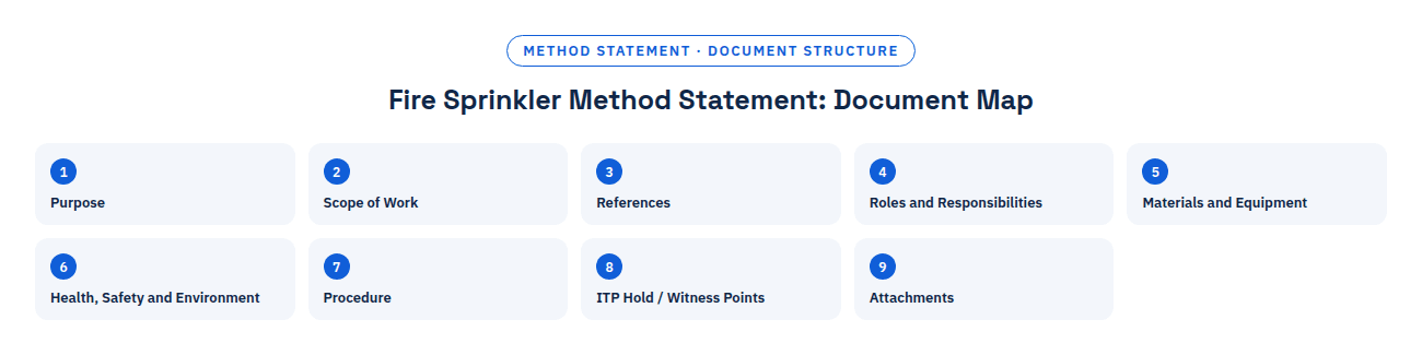
1. Purpose
This method statement defines the safe and compliant sequence for the installation, hydrostatic testing, flushing, and commissioning of the wet-pipe fire sprinkler system serving [building/zone name], in accordance with the approved shop drawings, project specification, and applicable codes.
2. Scope of Work
Covers supply, installation, testing, and commissioning of sprinkler system pipework, hangers/supports, sprinkler heads, alarm valves, and associated accessories from the fire pump room / riser to sprinkler heads in the areas defined in drawing [drawing number].
3. References
- Approved shop drawings and hydraulic calculations: [reference numbers]
- Project specification section: [reference]
- NFPA 13 – Installation of Sprinkler Systems (current adopted edition)
- NFPA 25 – Inspection, Testing, and Maintenance of Water-Based Fire Protection Systems
- Local Civil Defence / Authority Having Jurisdiction requirements: [to be inserted per project country]
- Approved material submittals: [reference numbers]
4. Roles and Responsibilities
| Role | Responsibility |
|---|---|
| Project Manager | Overall coordination, resource allocation |
| Site Engineer (Fire Fighting) | Supervises installation, ensures compliance with drawings and this MS |
| QA/QC Engineer | Verifies ITP hold/witness points, raises inspection requests |
| HSE Officer | Enforces PPE, permits, and safe work practices |
| Foreman/Supervisor | Direct execution and daily progress |
| Consultant/Client Representative | Witnesses hold points, approves test records |
5. Materials and Equipment
- Black steel pipes and fittings (schedule per approved drawing) — as per approved submittal
- Sprinkler heads (pendent/upright/sidewall as specified, correct temperature rating for each area — verify kitchen, plant room, and other high-ambient areas use the correct higher-rated head)
- Alarm check valve, flow switch, pressure switches, test-and-drain valve
- Pipe hangers and seismic bracing (if applicable), per NFPA 13 spacing tables
- Calibrated pressure gauges (0–300 psi range, valid calibration certificate)
- Hydrostatic test pump
- Welding/threading machine (if applicable) and consumables
6. Health, Safety and Environment
- Valid permit-to-work for hot work (welding/threading) and work at height
- PPE: safety helmet, safety shoes, gloves, eye protection; welding-specific PPE for hot work
- Fire extinguisher on standby during hot work
- Barricading and signage around hydrostatic test area during pressurization
- Toolbox talk conducted and recorded before start of activity
- Emergency response and evacuation route briefed to crew
7. Procedure
7.1 Pre-installation
- Verify approved shop drawings, hydraulic calculation, and material submittals are on site.
- Confirm builder’s work openings, sleeves, and supports are ready per drawing.
- Inspect incoming material against approved submittal (size, schedule, pressure rating) and reject non-conforming items.
7.2 Pipe installation
- Mark pipe routing as per approved drawing; obtain engineer’s approval on layout before fixing.
- Fix hangers and supports at spacing per NFPA 13 requirements for the pipe size, with provision for thermal expansion where required.
- Install pipework by welding, threading, or grooved coupling as specified, maintaining correct slope for drainage back to the low-point drain.
- Install branch lines and sprinkler drops per the approved sprinkler layout, maintaining specified sprinkler-to-sprinkler and sprinkler-to-obstruction clearances.
7.3 Sprinkler head installation
- Install sprinkler heads only after painting/finishing works in the area are complete, to avoid paint or debris contamination of the head (a common cause of head replacement and rework).
- Verify head type (pendent/upright/sidewall), orientation, and temperature rating match the approved drawing for that specific area before fixing.
- Do not install sprinkler heads until immediately before flushing and testing is complete, where practical, to reduce damage risk — otherwise protect installed heads until testing.
7.4 Flushing
- Flush the system before hydrostatic testing, per NFPA 13 — flush at a velocity sufficient to remove construction debris (minimum 10 ft/sec, with minimum flow rate per pipe diameter taken from the current NFPA 13 flushing table).
- Flush until discharge water runs visibly clear at the flushing outlet.
- Record flushing outlet, duration, and observed flow condition on the flushing certificate.
7.5 Hydrostatic pressure testing
- Isolate the system section to be tested; install test gauges at high and low points.
- Pressurize to 200 psi (13.8 bar), or 50 psi (3.4 bar) above the system’s normal working pressure — whichever is greater — and hold for 2 hours, per NFPA 13 (confirm against the current adopted edition).
- Inspect all joints, fittings, and connections for leaks during the hold period; rectify and retest any failure.
- Record start/end pressure, ambient temperature, and duration on the hydrostatic test certificate; obtain consultant witness signature at this hold point.
7.6 Commissioning
- Charge the system and confirm the wet alarm valve, flow switch, and pressure switches operate and transmit correctly to the fire alarm panel.
- Functionally test the test-and-drain valve and confirm alarm activation within the expected time.
- Verify fire pump start-up on pressure drop, where the sprinkler system is pump-fed (coordinate with the fire pump commissioning method statement/ITP).
- Complete the system-specific commissioning checklist and punch list; close out punch items before final handover.
8. Inspection and Test Plan (ITP) Hold/Witness Points
- H1 — Pipe routing and hanger spacing approval (before pipe fixing)
- W1 — Flushing (witness)
- H1/W2 — Hydrostatic test (hold point, consultant witness required)
- W3 — Commissioning and alarm functional test (witness)
Common Mistakes to Avoid
- Installing sprinkler heads before finishing/painting works are complete, leading to painted-over heads that must be replaced.
- Skipping or rushing the flushing step before hydrostatic testing — trapped debris is a leading cause of later sprinkler head or valve blockage.
- Using the wrong temperature-rated head in kitchens, plant rooms, or other high-ambient areas.
- Using uncalibrated or out-of-range pressure gauges for the hydrostatic test, invalidating the test record.
- Under-recording the test (short duration, missing ambient temperature) so the certificate gets rejected at submittal review.
- Sprinkler layout clashing with ducting and other ceiling services found late, because head positions were fixed from the RCP without a real walk-through against the as-built ceiling grid. Catch this at coordination, not at head-fixing.
- Measuring head spacing on a curved or irregular ceiling the same way as a straight one. Marking positions on the floor first (see our floor-marking method) catches spacing errors a ceiling-only layout misses.
- Fixing heads before both the architect and the civil defence/fire authority have signed off the RCP. A later architectural change to the ceiling grid after heads are fixed means re-work, not just paperwork.
Attachments
- Flushing certificate (blank format)
- Hydrostatic test certificate (blank format)
- Commissioning and functional test checklist
- Punch list format
- Calibration certificates for test gauges
After Handover: This Isn’t a One-Time Document
Once the system is commissioned, ongoing inspection, testing, and maintenance shifts to NFPA 25 — weekly/monthly gauge checks, quarterly alarm device tests, and annual full trip tests, depending on the component. If you’re handing this project to a facility management team, it’s worth pairing this method statement with an NFPA 25-based PM schedule so the acceptance testing isn’t disconnected from what happens in year one of operation.
This sample is a structural template for reference and adaptation — always align document numbering, referenced standards editions, and the local Authority Having Jurisdiction’s specific requirements to your actual project before submitting for approval.
Related Reading
- Marking Fire Sprinkler Locations: Why the Floor, Not the Ceiling
- Fire Pump Sizing Mistakes: NFPA 20 Explained
- Fire Hydrant System Method Statement: Installation, Testing & Commissioning
- Fire Protection Systems: The Complete Guide
- Fire Pump Method Statement: Installation, Testing & Commissioning
Need the paperwork for the rest of the system?
While the sprinkler method statement is still being built, two companion documents are ready now: the Fire Pump Method Statement (NFPA 20) and the Fire Hydrant Method Statement (NFPA 14/24) — each a fully editable Word document with checklists, test records and an ITP, $7 each.