BuildMEP emergency-lighting troubleshooting guide
A replacement luminaire can light up perfectly and the fault still won’t clear. This guide walks through why that happens, how to work out what the system is actually monitoring, and what evidence you need before the work order can be closed.
Decision brief
Don’t close out the fault just because the replacement light comes on. A visible lamp check only proves part of the repair—the monitoring system also has to recognize the expected device or channel, complete its required test, and settle the correct location back into a healthy state without kicking off new faults somewhere else.
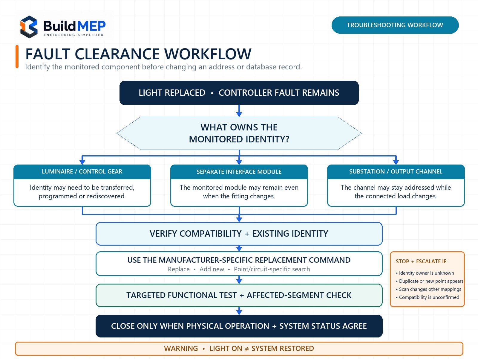
Before you touch an address or run a discovery command, work out what architecture is actually installed. The monitored point might be the luminaire itself, an addressable control gear or lamp-test controller, a substation output, or nothing more than a logical database entry. Replacement steps depend on which one you’re dealing with, since they’re manufacturer- and product-specific.
Field symptom: the light works, but the system disagrees
A technician swaps out a faulty emergency fitting and confirms it lights up. The controller or monitoring software, though, keeps reporting a luminaire fault, a missing point, a duplicate address or a circuit warning. Running the same test again doesn’t clear it.
The real gap usually isn’t between “working” and “broken.” It’s between optical operation, emergency operation, device identity, system mapping and recorded test status—and any one of these can pass while another fails.
First identify what is addressable
“Addressable emergency lighting” isn’t one architecture—it covers several. Don’t assume an address belongs to the fitting just because the software happens to display a fitting location.
Individual monitored luminaire
The luminaire or its emergency control gear carries a hardware, factory- or software-assigned identity. Replacing it may mean transferring or reprogramming that identity, then running the product’s add/search procedure.
Addressable interface module
A separate monitoring module can stay in place, or get replaced independently of the luminaire itself. Change only the light source or slave fitting, and the monitored address may not move at all.
Substation or output channel
Here the system is watching a channel that feeds one or more luminaires, not the fittings themselves. The channel keeps its identity even as the connected fitting or configured load changes.
Eaton’s ZB-S central battery system, for instance, can individually monitor CG-S luminaires straight through the supply cable, with up to 20 address positions per circuit. ABB’s EMEX architecture works differently: it can use addressable LTC interfaces or monitored substation outputs, and ABB also documents an MXD4 arrangement where an unmodified slave luminaire can be swapped out without touching the addressable system at all. These are two very different replacement problems, even though both just show up as named light points on screen.
Safety and configuration boundary
Emergency lighting is a life-safety system—treat it that way. Use the approved impairment, permit, isolation and reinstatement procedure, and confirm how escape routes stay protected while a circuit, controller or central battery output is unavailable. Work only within the technician’s authorization and the manufacturer’s instructions.
Before changing any configuration, export or record the current database, controller state, circuit, logical address, point name and active faults. Don’t reach for a system-wide “search all,” initialization or factory-reset command as a casual troubleshooting step—some controllers explicitly warn that a full search overwrites the existing configuration, while a “search new” function leaves already-addressed devices alone.
Read the fault before replacing another part
| Software symptom | Likely cause to check | Evidence to collect | Next action |
|---|---|---|---|
| Original point remains missing or offline | Replacement identity never enrolled, wrong circuit, an open communication path, or an unpowered interface | Old and new IDs, circuit/output, wiring continuity, controller discovery result | Follow the model-specific replace/add procedure, then fix the communication or supply fault before re-testing |
| Duplicate-address warning | Two devices share one hardware or logical address | Address-switch positions, programmed short addresses and controller device list | Track down both devices, then correct the duplicate under an approved configuration change |
| New point appears, old location remains faulty | Device got discovered but never mapped to the existing database record or physical location | New ID, old point name, floor plan and controller mapping | Link the verified device to the correct location—don’t just rename an unproven point |
| Lamp operates, but functional test fails | Emergency changeover, monitoring feedback, control gear, load setting or test state is off | Normal and emergency operation, test command, feedback status, compatible load data | Confirm product compatibility and the emergency operating sequence, then dig into the control gear or interface |
| Several points change after a scan | Database got reinitialized, logical addresses got reassigned, or circuit mapping changed | Configuration backup, before/after device lists and affected circuit | Stop making further changes, compare against the approved database, and escalate to the system specialist |
| Point is healthy, but location is wrong | Database name, drawing reference or physical label doesn’t match the installed device | Local function test, physical label, floor plan and point text | Correct the asset record under change control, then re-verify the location from the controller |
Replacement and fault-clearance workflow
-
Capture the original state before removal.
Write down the exact controller, cabinet or gateway; the circuit, loop, line or substation; the displayed address or channel; point name; fault code; test status; and the old fitting, driver or monitoring-module model. Photograph any labels you’re permitted to, and export the relevant configuration or device list.
Hold point: you can reconstruct the original monitored point from this record alone. -
Identify the monitoring boundary.
Use approved drawings, the controller manual and product labels to work out whether the replaceable item holds the address, whether a separate module stays in place, or whether the software is actually monitoring a substation output. Don’t infer the architecture from the user-interface wording alone.
Check: the team can point to the exact component that owns the address or channel. -
Confirm replacement compatibility.
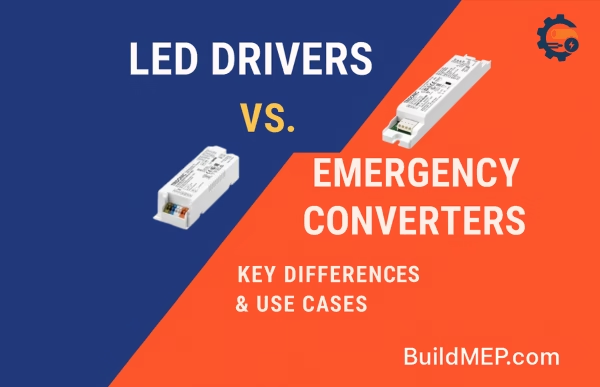
Compare supply type, central-battery compatibility, lamp or LED load, emergency operating mode, monitoring interface, control gear, communication protocol and manufacturer-approved replacement instructions. A fitting that lights up fine on normal power isn’t automatically compatible with the test and monitoring system. For component context, see LED drivers versus emergency converters.
Check: the installed emergency-lighting architecture actually supports this replacement. -
Install under the approved isolation and impairment plan.
Preserve circuit integrity, polarity, protective earth, fire-resistant wiring and local labels as applicable. If the monitored interface stays in place, don’t disturb its address unnecessarily. If it’s replaced, set or associate its identity exactly as the manufacturer requires.
Check: terminations, identification and physical installation pass the local inspection. -
Use the narrowest safe commissioning command.
Select the documented “replace,” “add new,” “luminaire search,” “commission device” or equivalent procedure for the exact product, and favor a circuit- or point-specific operation wherever it’s supported. Preserve the approved database and stay away from system-wide discovery unless the method explicitly requires it and a recovery plan is already in place.
Hold point: the expected point appears once, at the expected circuit and location. -
Check the whole affected segment.
Review missing, duplicate, new and renamed points on the same circuit, line or substation. A green status at the replacement point doesn’t mean much if the same operation displaced another asset record or created an unassigned device.
Check: no unexplained new fault or mapping change exists on the affected segment. -
Run the required functional test.
Command the test from the approved controller or procedure and physically witness the correct fitting responding at its actual location. Verify the changeover or emergency output, the feedback, and the return to the expected state. Run a duration test only when the applicable standard, commissioning plan or manufacturer procedure requires it, and plan around battery recharge time and the temporary impairment it creates.
Acceptance: the local response and the controller result refer to the same asset. -
Close with two independent confirmations.
Record the physical result and the system result separately. Attach the before/after point data, the replacement model or serial number, the test result, and the names of the technician and verifier. If either confirmation is missing, log an open defect or a formally managed impairment rather than recording the job as complete.
Acceptance: physical operation, emergency test, software health and records all agree.
Worked fault-clearance example
Assumed example: a central battery circuit reports “Circuit 5, luminaire 07 fault.” The replacement light illuminates on normal supply, but address 07 still isn’t showing up. The installed monitoring gear uses hardware address switches, and the old module was recorded as 07 before removal.
- The verifier confirms the address belongs to the emergency control gear, not just the physical housing.
- The replacement control gear is checked for system compatibility and turns out to be sitting at its uncommissioned/default setting.
- Following the manufacturer’s isolated setup procedure, it’s assigned to the required, unused address 07.
- A circuit-specific luminaire search is run, and the controller reports exactly one device at 07—no duplicate.
- A targeted functional test is commanded and witnessed right at the recorded location.
- The point comes back healthy, the affected circuit shows no additional fault, and both results are attached to the work order.
Close-out decision: only close the work order once address 07 is healthy, the correct physical fitting has passed its emergency functional test, and the circuit shows no unexplained device or mapping change.
This is a method example, not a universal address-setting instruction—plenty of systems use factory identities, logical short addresses or monitored output channels instead of hardware switches.
Work-order close-out that prevents repeat faults
Physical confirmation
- Confirm the installed make, model and compatible control gear.
- Witness both normal operation and the required emergency operation.
- Record the exact room, fitting label and drawing reference.
- Confirm covers, legends, diffusers and local indicators are restored.
System confirmation
- Confirm the expected address or channel is healthy.
- Confirm the point name matches the witnessed location.
- Confirm there’s no duplicate, missing or unexplained new point.
- Attach the controller test result and verifier identity.
If the computerized maintenance management system (CMMS) only has one generic “completed” field, add separate mandatory fields for physical restoration and monitoring-system restoration. That second sign-off should come from a person authorized to use and interpret the controller—it shouldn’t be inferred from the electrician’s visual check.
Stop and escalate when
- The system architecture or address owner can’t be confirmed.
- There’s no current configuration backup or approved device schedule.
- A scan changes multiple point identities or locations.
- The replacement product isn’t listed as compatible.
- A duplicate address can’t be physically located.
- The controller, battery system or communication circuit has another active fault.
- The required test would leave an occupied escape route inadequately protected.
- The task requires passwords, programming tools or authority outside the assigned scope.
Frequently asked questions
Should I give the new device the old address?
Only when the installed product’s replacement procedure requires that transfer and the old address is confirmed unused. Some devices are factory pre-addressed or identified by serial number; others use a configurable hardware or logical address. Never create a duplicate just to make the screen look familiar.
Should I run “search all” if the fault will not clear?
Not as a first response. On some systems, a full search can overwrite the existing configuration or reassign logical addresses without warning. Back up the database, read the controller manual and use the narrowest supported replacement or “search new” function.
Can the work order be closed if the light works but the controller fault remains?
No. The physical repair may be complete, but the monitored life-safety system still has an unresolved defect. Keep it open, or run it through the site’s formal impairment and escalation process, until the expected point and test result are both restored.
Can replacing one luminaire create faults elsewhere?
It can, if the commissioning action changes addresses, mappings or circuit configuration. It’s not an automatic consequence of physical loop position. Review the affected segment after any discovery or database change and follow the exact manufacturer procedure.
Evidence trail and limits
- BSI, BS EN 50172:2024, Emergency escape lighting systems: the current UK edition, covering installation requirements alongside verification, operation, maintenance documentation and testing. Check which national edition and local authority requirements actually apply to your project.
- IEC 62034:2012, Automatic test systems for battery-powered emergency escape lighting: sets performance and safety requirements for automatic test systems, including functional and duration testing and failure monitoring. Whether it applies depends on the installed system.
- IEC 60598-2-22:2021, Luminaires for emergency lighting: covers particular requirements for emergency luminaires. It doesn’t replace the system manufacturer’s commissioning instructions.
- Eaton CEAG, ZB-S Mounting and Operating Instructions, December 2020: a product example for luminaire add/remove, search, duplicate-address behavior and point assignments in an individually monitored central battery system.
- Eaton, CGLine+ Web Compact Controller manual, May 2024: a self-contained system example showing the difference between “search all” and “search new.” It’s included to demonstrate product variation, not as an ECBS procedure.
- ABB Emergi-Lite, EMEX Test technical reference: a central-system example using substations and factory pre-addressed LTC interfaces, including an arrangement where an unmodified slave luminaire can be changed without disturbing the addressable system.
Evidence reviewed 24 August 2026. Address allocation, reset behavior, discovery commands, impairment controls and acceptance tests all stay product-, project-, contract- and jurisdiction-specific. Check the exact controller and module manuals before changing a live installation.