Part of Fire Protection Systems: The Complete BuildMEP Guide →
Most weak fire hydrant method statements treat the work as a larger sprinkler installation. In practice, the package can cross several boundaries: private underground fire mains, yard hydrants, building standpipes or wet risers, hose stations, valves, pump connections, civil trenches and heavy lifting. Each boundary changes the approved material, joining method, inspection record and acceptance test.
This guide is based on a real marine/coastal infrastructure installation and is deliberately written as a project-adaptable workflow. It shows what must be decided and recorded without presenting one pipe material, joint detail, support spacing or test pressure as universal.
Free download: Fire Hydrant Pre-Commissioning Checklist (Word)
37 checks to complete before flushing and hydrostatic testing. Enter your email and the download opens right after. You will also get the BuildMEP monthly engineering briefing, one email a month, and you can unsubscribe any time.
What Actually Differs From a Sprinkler Method Statement
A hydrant or wet-riser package commonly introduces four controls that deserve their own method:
- Underground work: trench approval, bedding, cover, separation from other services, approved fire-main pipe and restrained transitions must be inspected before concealment.
- Different joining systems: steel fabrication, flanged or listed mechanical joints, and PE heat fusion each require different procedures, qualifications and records. The approved pipe system—not a convenient diameter shortcut—governs the joint.
- Handling and lifting: large feeder spools, valves and hydrants need planned lifting points, temporary supports and protection of linings or galvanized/coated surfaces.
- Acceptance boundaries: underground mains, standpipes, pump suction/discharge piping and combined systems can fall under different adopted standards. Test packs must state exactly which section is being accepted.
The method statement should therefore be a controlled execution document: it links approved drawings and materials to the installation sequence, inspection hold points, test instruments, acceptance criteria and records that will enter the handover file.
Standards: Map the Scope Before Copying a Test Figure
The applicable edition is the one adopted by the authority having jurisdiction (AHJ) and referenced by the contract—not automatically the newest publication. For an NFPA-based project, the responsibility map normally starts like this:
| Work boundary | Typical technical basis | Method-statement decision |
|---|---|---|
| Private underground fire main and private hydrants | Adopted NFPA 24 plus approved civil/material standards | Pipe approval, trench and restraint details, flushing, hydrostatic test and contractor’s certificate |
| Standpipe, wet-riser and hose system | Adopted NFPA 14 or the applicable local standard | System classification, valves/outlets, installation, flow and acceptance testing |
| Fire pump and connected suction/discharge work | Adopted NFPA 20 and the listed pump assembly requirements | Protect equipment during flushing/testing and coordinate pump acceptance |
| System after handover | Adopted NFPA 25 and the owner’s maintenance programme | Transfer baseline records; do not use maintenance criteria as a substitute for installation acceptance |
Material standards such as ISO 4427 for PE piping or BS EN 10255 for steel tubes apply only when specified and when the complete pipe, fitting and joining system is approved for the service. Local fire codes, civil specifications, water-authority rules, product listings and manufacturer instructions can add or change requirements.
Sample Method Statement: Fire Hydrant System Installation, Testing & Commissioning
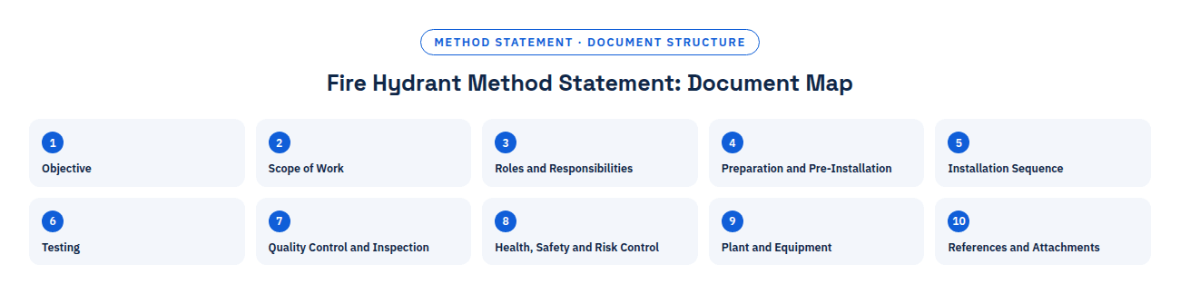
1. Objective
To ensure correct materials and equipment are used, and agreed procedures followed, during fabrication, installation, and testing of the fire hydrant system.
2. Scope of Work
Fabrication, installation, and testing of the fire hydrant/wet-riser piping system — underground feed mains, above-ground feeder mains and standpipes, hydrants, and associated valves and accessories — to achieve the specified quality of workmanship.
3. Roles and Responsibilities
| Role | Responsibility |
|---|---|
| Project Manager | Overall project integration, cost/time control, risk management |
| Project Engineer | Technical submissions, drawing approvals, procurement follow-up, HSE/ISO compliance |
| Site/Installation Engineer | Coordination and execution of fabrication and installation, day-to-day technical direction |
| QA/QC Engineer | Manages inspection and test procedures, quality of installed work |
| HSE Officer | Site safety inspection, hazard analysis, incident investigation, emergency drills |
| Welder (qualified for the approved process and joint) | Holds a current qualification within the approved WPS range; records joint identification and executes the weld accordingly |
| Pipe Fitter | Pipe system layout, support/hanger selection, cutting and threading |
4. Preparation and Pre-Installation
4.1 Material and drawing approval
Material submittals, compliance evidence and samples required by the specification are approved before procurement or installation. The procurement schedule should allow the project’s actual review period rather than relying on a generic lead time. Approved samples are identified with the supplier, approval status and intended use so delivered material can be checked against the controlled reference.
Shop drawings are produced from the latest coordinated design and services drawings, checked against other trades to avoid clashes, and the current approved revision is kept available at the installation location — every worker involved is briefed on what’s approved before they install against it.
4.2 Material requirements (worked example — confirm your own project’s schedule)
- Underground pipes: the approved fire-main pipe system; where PE/HDPE is permitted, use the specified pressure class, dimension ratio, fittings and joining procedure as one compatible system
- Above-ground branch/hose-reel piping: galvanized steel (GI), to the project’s adopted steel tube standard (e.g. BS EN 10255 or equivalent)
- Drains, air vents, test points: galvanized steel, same standard as above
- Fittings: hot-dip galvanized malleable iron (bends, elbows, tees, unions, reducers) and galvanized mild steel flanges, matched to the approved material submittal
- Supports: hot-dip galvanized anchors, threaded rod, loop hangers, girder clamps
- Jointing/finishing: approved thread sealant/pipe jointing compound, zinc phosphate anti-corrosive primer, enamel finish paint
4.3 Storage and handling
- Pipes stored clear of the ground on supports or pallets, segregated by diameter, stacked no higher than roughly 1.7m, covered from weather, and kept clear of traffic routes and emergency access.
- Flammable paints and thinners stored separately, in a ventilated area away from direct sun and high shelving, with a fire extinguisher on hand.
- Incoming material inspected against the approved submittal on arrival, and again by the site supervisor at the point of issue for installation — a second check at the point of use catches substitutions or damage that slipped past the first.
5. Installation Sequence
5.1 Pipe cutting and fabrication
Pipes are cut to exact length from the approved shop drawing dimensions using a pipe cutter (machine or manual); the cutting area is protected from oil splash, and scale/slag/debris is cleared from the cut end before further machining.
5.2 Welding and coating repair
Welding is used only where the approved steel pipe system and project documents permit it. Before production work, approve the Welding Procedure Specification (WPS), supporting procedure qualification where required, welder qualifications, joint details, consumables, inspection method and acceptance criteria. The qualified range must cover the actual pipe material, wall thickness, diameter, process and welding position; a generic “6G welder” label does not by itself approve every project joint.
Pipe ends are identified, cut, prepared and aligned to the approved WPS. Coating, moisture, oil and other contamination are removed from the controlled weld area. Root, fill and cap passes, preheat/interpass controls and consumables follow the WPS—not a site rule of thumb for bevel, gap, electrode or reinforcement. Each weld receives a traceable joint number and the specified visual examination or non-destructive examination before coating repair.
Hot work on galvanized steel needs specific fume controls: zinc-bearing coatings can generate zinc-oxide fumes, so the risk assessment must address ventilation, exposure control, respiratory protection where required, fire watch and removal of combustible materials. After acceptance, restore the damaged corrosion protection with the approved surface preparation and repair coating system, covering the heat-affected area to the specified dry-film thickness.
5.3 Pipe brackets and supports
Support type, rod size, anchor, spacing and seismic restraint are taken from the approved support schedule and calculations. Do not copy a spacing table without checking pipe material and schedule, filled weight, valve and fitting loads, building structure, movement, corrosion category and the adopted fire-protection standard.
- Support valves, hydrant risers, backflow assemblies and other concentrated loads independently where required.
- Keep joints, drains, test points and operating handles accessible; do not place a hanger where it prevents maintenance.
- Use approved anchors and edge distances; scan concrete before drilling and obtain structural approval for exceptional loads.
- Check alignment and temporary support before releasing a lifted spool. Pipe joints are not lifting points or substitutes for permanent support.
- Record support inspection before painting, ceiling closure or trench backfill hides the work.
5.4 Installation of feed mains and standpipes
Mark routes from the current approved coordinated drawing and verify elevations, access, valve operation and clashes before drilling or fabrication. Fabricate large spools in manageable lengths where workshop control improves quality, then lift them under an approved lifting plan using suitable slings and protected contact points.
Select threaded, welded, flanged, grooved or listed mechanical joints from the approved pipe system and manufacturer instructions. There is no universal 65 mm or 2½-inch rule that overrides the pipe standard, wall thickness, fitting listing or project specification. Inspect threads, flange alignment, gasket type, bolt tightening and grooved-end dimensions to the relevant approved procedure. Fit temporary caps to every open end and maintain internal cleanliness through each work stage.
5.5 Underground pipe laying and PE fusion
Approve the trench route, safe excavation method, bedding, cover, separation, warning/marker system, thrust restraint and transition details before pipe placement. Inspect the trench formation and remove sharp material that could damage the pipe or coating. Keep joints, fittings and restraints visible until their required inspections and tests are accepted.
Where PE pipe is approved, use trained operators and maintained fusion equipment with the pipe/fitting manufacturer’s qualified parameters. For butt fusion, clean, clamp, face and align the ends; control heater condition, temperature, fusion pressure and cooling time; then inspect and record the bead. Use electrofusion only with approved compatible fittings and procedures, including scraping/preparation, alignment, scan data and cooling time. Record operator, machine, date, joint number, parameters and inspection result so every buried joint remains traceable.
Transitions between PE and metallic pipe need the approved adaptor, restraint and corrosion protection. If metallic pipe is permitted underground, apply the specified coating/wrapping system and inspect it before backfill; galvanizing alone should not be assumed to satisfy the buried-service protection requirement.
5.6 Painting
Corrosion spots are cleaned and re-primed before painting proceeds. The surface needs to be free of dust, moisture, and metal particles; one coat of anti-corrosive (etching) primer goes down first, followed by two finish coats, with a full dry-and-inspect cycle between each coat rather than rushing coats on top of each other.
6. Testing
6.1 Hydrostatic pressure test
Prepare a test pack before pressurization. It should identify the exact test boundary on a marked-up drawing; blind/blank locations; high-point vents and low-point drains; excluded components; calibrated gauge or data-logger details; test medium; filling, stabilization and pressurization steps; approved pressure and duration; acceptance criteria; witness points; and the safe method of depressurization and disposal.
Confirm that every component inside the boundary is rated for the test pressure and isolate equipment that is not. Fill from a controlled low point, vent trapped air, inspect restraints and raise pressure gradually. Establish an exclusion zone: stored energy, temporary blanks and trapped air can make a water test hazardous even though it is not pneumatic.
Judge the result only against the approved acceptance basis. Record start/end time, pressure, ambient or water temperature where relevant, gauge identification, any permitted make-up water, visible leakage and corrective action. For PE piping, use the approved PE-specific procedure and stabilization method; pressure decay caused by viscoelastic expansion must not be evaluated with an improvised steel-pipe rule. Repair failures, re-inspect the repair and repeat the affected test—never tighten or repair a pressurized joint.
6.2 Flushing
Define the required flushing sequence, flow criterion and discharge route from the adopted standard and approved test plan. Protect pumps, meters, backflow devices and downstream equipment from construction debris; fit temporary connections or strainers where the approved procedure calls for them. Secure hoses and outlets, control erosion and flooding, and obtain environmental approval for the discharge location.
Flush each accepted section through a safe, observable outlet until the specified flow condition and cleanliness criteria are achieved. “Water looks clear” is useful field evidence but is not a substitute for a required flow rate, velocity or recorded acceptance certificate. Record the water source, route, outlet, start/end time, achieved flow evidence and witness.
6.3 Pre-commissioning and commissioning
Before commissioning: confirm all equipment is clean and free of debris, all automatic controls and safety devices are inspected and serviceable, and instruments are correctly installed and reading accurately. Commissioning itself confirms every service and control system is functioning, properly sequenced, and interlocked as designed — not just that water flows.
6.4 Final acceptance test
Run after commissioning is complete, ahead of the Performance/Completion Certificate, and repeated if the Authority Having Jurisdiction requires its own witnessed test.
7. Quality Control and Inspection
Inspection principle: The ITP should turn the method into evidence. The most useful control is not another narrative paragraph but a traceable record at each irreversible stage.
| Stage | Minimum evidence | Typical control point |
|---|---|---|
| Material receipt | Approved submittal, certificates/listings, size/rating, condition and traceability | Review before issue |
| Trench and bedding | Route, depth/cover, separation, formation, bedding and survey | Hold before pipe placement or concealment |
| PE fusion | Operator/machine qualification, joint log, parameters, bead/EF record | Surveillance plus joint traceability |
| Steel welding | WPS, welder qualification, weld map, visual/NDE result and coating repair | Hold before coating where specified |
| Supports and restraints | Approved detail, anchor/support inspection, valve and thrust restraint | Inspect before closure |
| Hydrostatic test | Approved test pack, calibrated instruments, marked boundary and signed result | Witness/hold as the ITP requires |
| Flushing and functional test | Flow evidence, discharge record, valve/hydrant operation and defect closure | Witness |
| Handover | As-builts, certificates, test sheets, O&M data, spares and training | Final review |
8. Health, Safety and Risk Control
Use the project HSE plan, task risk assessments and permits, but make the controls specific to this work:
- Excavation: service detection, permit, safe access, spoil setback, shoring/benching, water control and daily competent-person inspection.
- Lifting: verified load and radius, certified equipment/tackle, lift plan, tag lines, exclusion zone and temporary support before release.
- Hot work: permit, fire watch, gas testing where applicable, screens, housekeeping and ventilation/exposure controls for zinc-bearing galvanized surfaces.
- Pressure testing: rated blanks and hoses, remote pressurization where practical, exclusion zone, controlled venting and a prohibition on adjustment while pressurized.
- Flushing: restrained discharge, drainage capacity, erosion/flooding control, communication and protection of the public and adjacent equipment.
9. Plant and Equipment (representative — adjust to your scope)
Chop saw, hole-cutting tool, pipe vise, arc welding plant, angle grinders, HDPE butt-welding and electrofusion machines, HDPE pipe cutters, crane truck, bucket boom truck / boom lift, forklift, excavator, pipe wrenches, spirit levels, hammer/rotary drill, and standard electrical test equipment (multimeter, insulation tester) for any associated controls.
10. References and Attachments
- Project technical specification, approved design/shop drawings, hydraulic calculations and material submittals
- NFPA 24, Standard for the Installation of Private Fire Service Mains and Their Appurtenances—use the edition adopted by the AHJ
- NFPA 14, Standard for the Installation of Standpipe and Hose Systems—use the adopted edition
- NFPA 20 where fire-pump suction/discharge piping and pump acceptance are within scope; NFPA 25 for inspection, testing and maintenance after handover
- Plastics Pipe Institute, Handbook of PE Pipe—joining, installation and PE-specific testing guidance
- OSHA guidance on welding fumes—zinc-oxide exposure from galvanized steel; apply the governing local safety regulations
- Approved ITPs, WPS/PQR and welder qualifications, fusion procedure and joint logs, calibrated-instrument certificates, test packs and handover forms
Lessons Worth Carrying Into Your Own Method Statement
- Map the standard to the physical boundary. A private main, standpipe and fire pump are connected, but they are not automatically accepted under the same section or test record.
- Approve the complete joining system. Pipe size alone does not decide whether a joint is threaded, welded, flanged, grooved, mechanical or fused.
- Do not bury missing evidence. Trench, restraint, fusion and coating records are cheapest to obtain while the work is still exposed.
- Protect the coating and the welder. Galvanized/coated steel needs both an approved repair system and effective fume controls.
- Test in traceable zones. A marked boundary, calibrated instrument and defined acceptance criterion make failures diagnosable and results defensible.
This guide provides an adaptable execution framework, not a universal submission. Confirm the adopted codes, component listings, material/jointing procedures, test criteria and AHJ requirements for the actual project.
Technical review: 20 September 2026.
Related Reading
- Fire Pump Sizing Mistakes: NFPA 20 Explained
- Fire Protection Systems: The Complete Guide
- Fire Pump Method Statement: Installation, Testing & Commissioning
Editable document
Need this as a submittal-ready method statement?
This article covers the theory and sequence. If you need an editable Word document to submit—welder qualification tables, hanger/support sizing, hydrostatic-test record forms, and a full ITP with hold points—the Fire Hydrant Method Statement ($7) is ready to adapt with your project details.
Get the Method Statement →