Part of Fire Protection Systems: The Complete BuildMEP Guide →
BuildMEP practical fire-protection field guide
A floor mark can speed up sprinkler set-out and make it easier to verify, but it's not the design itself. Reliable layout starts with the latest approved sprinkler working drawing, an agreed building-control system, and a recorded check before piping, drops or ceilings make correction expensive.
Decision brief
Use manual grid-and-offset layout for a modest number of points in simple orthogonal geometry, as long as each point ties back to stable building control and gets checked independently.
Use instrument-based layout when the floor plate is curved or irregular, the point count is high, coordinated model points already exist, or chained tape measurements would stack up error.
Treat the floor mark as an intermediate control point. Before final installation, confirm the actual ceiling plane, elevation, sprinkler orientation and obstruction conditions. A correct horizontal point on the slab can still produce an incorrect sprinkler at the ceiling.
The control hierarchy: what actually governs the mark
The reflected ceiling plan (RCP) is a genuinely useful coordination background, but it's not normally the document that authorizes a sprinkler location on its own. The approved fire-sprinkler working or shop drawing carries the system design; the coordinated RCP or BIM model shows how that design relates to lights, diffusers, detectors, access panels and architectural modules.
- Adopted requirements
Code, standard, AHJ conditions and approved specifications - Approved sprinkler drawing
System layout, pipework, sprinkler data and design basis - Coordinated model or RCP
Ceiling geometry and multidisciplinary interfaces - Verified site control
Grid, benchmarks, survey points, coordinates and level - Physical field mark
A temporary installation reference with point identification
If the field mark disagrees with anything higher up the chain, stop and sort out the discrepancy first. A paint mark on its own is never evidence that a relocation was approved.
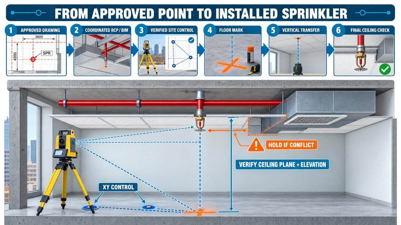
Coordinate first—but don't move sprinklers by eye
Sprinkler coordination isn't just an aesthetic exercise. The final location has to satisfy the adopted design rules for the selected sprinkler and ceiling condition, including spacing, permitted distance from walls, coverage limitations, obstructions, orientation, deflector position and the exact product listing. Those checks shift with sprinkler type, hazard, ceiling geometry and the adopted edition, so don't treat a generic spacing number as a universal site rule.
A conflict with a light or diffuser doesn't automatically make either item immovable. A sprinkler can sometimes be relocated, but only once the responsible designer checks the code, listing, coverage, obstruction and hydraulic consequences, and the project change-control process signs off on the revision. Moving another ceiling service instead can just as easily create access, performance or architectural problems of its own. Coordination should end in a documented solution — not an informal turf war between trades.
| Control item | What to verify | Why an XY floor point is not enough |
|---|---|---|
| Ceiling geometry | Level, slope, step, cloud, coffer, bulkhead and final ceiling module | The floor and finished ceiling may not be parallel or vertically aligned. |
| Sprinkler data | Type, orientation, temperature classification, K-factor, response and listing | Different sprinklers have different permitted installation arrangements. |
| Obstructions | Ducts, beams, cable containment, lights, signs, diffusers and architectural features | A clear point on the floor may sit below an obstruction at ceiling level. |
| Vertical position | Finished ceiling elevation, deflector relationship and drop/nipple arrangement | Horizontal accuracy does not establish the correct sprinkler elevation. |
| Pipe and support route | Branch line, arm-over, hangers, sleeves, access and structural interfaces | A head point may be reachable only through an unbuildable pipe route. |
When floor marking works—and when it needs extra control
Floor marking earns its keep when the slab is accessible, the final ceiling isn't installed yet, and a point can be transferred vertically without any ambiguity. It gives the site team a visible reference that's a lot easier to measure, label and inspect than an overhead mark buried in a congested void.
It needs extra control where ceilings are sloped, stepped, coffered, floating or curved; where raised floors or temporary protection might cover the mark; where the point has to transfer around an obstruction; or where the ceiling grid isn't vertically aligned with the slab reference. In these cases, hang onto the coordinate record and run a dedicated final-ceiling or grid check. Direct ceiling layout can be the better call when the approved ceiling plane is already stable and the instrument can project to it safely.
Responsibilities and records
| Role | Primary responsibility | Expected record |
|---|---|---|
| Sprinkler designer / contractor | Issue the current approved layout, point data and sprinkler schedule; assess proposed relocations. | Approved drawing, calculation/change reference and point schedule |
| BIM / CAD coordinator | Resolve ceiling interfaces and preserve the correct coordinate system, units and model revision. | Federated view, clash status and controlled export |
| Survey / layout technician | Verify control, set out points, monitor the instrument and record observations or deviations. | Setup/check report and staked-point file |
| Site engineer / QA-QC | Check revision, sampling or closure method, mark identity and hold-point release. | Inspection request, checklist and photographs |
| Consultant / AHJ where required | Review or witness in accordance with the approved ITP and local approval process. | Inspection response or approved change |
Pre-layout hold-point checklist
Don't start just because the model "looks coordinated." Only release set-out once the information and the physical controls actually agree.
- Latest approved sprinkler drawing and revision confirmed
- RCP/BIM coordination status confirmed for the same revision
- Point IDs and sprinkler types included in the schedule
- Units, origin, rotation, level and coordinate system checked
- Primary and secondary building-control points verified
- Finished ceiling elevations and local geometry available
- Instrument calibration and site check current
- Floor access, lighting and line of sight suitable
- Marking material approved for the substrate and finishes
- Independent verification method and tolerance agreed in the ITP
- Superseded drawings and point files removed from field use
- RFI/change path understood by the installation team
Choose the layout method from geometry and risk
| Method | Suitable use | Main risk | Required check |
|---|---|---|---|
| Tape and two offsets | Simple orthogonal areas with stable grids and a limited point count | Chained dimensions, skewed references and accumulated error | Two independent dimensions or a closure check from separate control |
| Laser distance meter | Short, unobstructed internal distances and secondary verification | Wrong target surface, angular error or an unverified datum | Confirm the reference plane and cross-check against grid/control |
| Point/plumb laser | Vertical transfer between a verified floor point and ceiling plane | Assuming “up” resolves ceiling elevation or obstruction compliance | Check plumb, ceiling level, projection path and local clearance |
| Robotic total station or digital layout tool | Curved/irregular geometry, high point counts and coordinated model points | Wrong file, units, origin, rotation, backsight or instrument movement | Known-point check, periodic backsight/control check and recorded deviations |
| Final ceiling/grid verification | All methods before final fixing, especially irregular ceiling conditions | A correct floor mark transferred to the wrong ceiling module or plane | Compare final sprinkler centre and elevation with the approved coordinated layout |
Digital layout software can push coordinated AutoCAD, Revit or model points straight into the field and hand back staked points for reporting. That's a real boost to traceability, but it doesn't validate the design or fix a wrong coordinate system on its own. For drawing preparation, BuildMEP's AutoCAD total-length LISP guide also comes in handy when checking quantified branch-line geometry.
Field workflow: drawing to checked installation point
- Freeze the approved input. Record the sprinkler drawing number, revision, model/export version, level and date. Pull superseded copies off tablets and out of site folders.
- Prepare a controlled point schedule. Give every sprinkler a unique point ID. Include X/Y or grid offsets, level, finished ceiling elevation, sprinkler type/orientation and drawing reference.
- Verify site control. Check at least two suitable control points, or follow the project survey procedure, before marking production points. Don't rely on a finished wall as the sole datum unless its surveyed position has been verified.
- Set out using the selected method. For manual work, skip chained dimensions and use independent offsets instead. For digital work, verify file units, orientation, backsight and a known check point before proceeding.
- Mark and identify the centre. Use a precise cross, centre punch or approved symbol—not a wide paint cloud. Add the point ID, level/status and direction note where needed.
- Perform an independent check. Re-measure from separate control, close the geometry, or reobserve points under the approved QA plan. Recheck instrument control periodically through the layout session.
- Verify the vertical transfer. Confirm the ceiling plane, grid module, sprinkler elevation, orientation and unobstructed projection. Don't assume the slab point defines the finished head position.
- Record discrepancies. If a coordinated point conflicts with an installed service or ceiling condition, tag it as on hold and raise an RFI or controlled coordination change. Never just "make it fit" in the field.
- Update the record. Import or annotate staked/as-laid points, deviations and superseded marks on the controlled CAD/BIM record. Photos help, but they're no substitute for point data.
- Release the hold point. Get the inspection or sign-off the ITP requires before drops are fixed or ceiling work seals off the control.
Make the mark readable—and make the record durable
Spray paint works fine on a permitted substrate, but how long it lasts is project-specific. Marks can end up buried under screed, protection boards, dust, raised floors or later trade markings. Use a project legend and check paint compatibility, housekeeping rules and finish requirements before you start spraying.
At the point
Show a precise centre, point ID, service symbol and status. Keep the centre visible after the label is added.
On the schedule
Retain coordinates/offsets, level, ceiling elevation, sprinkler data, drawing revision and set-out date.
In the record
Capture checked/as-laid status, deviation, RFI/change number and the person who verified the point.
A consistent compliance-matrix approach can help keep approvals and inspection evidence under control. See BuildMEP's submittal checklist and compliance matrix template.
Worked field case: curved atrium ceiling
Take an atrium with 24 pendent sprinklers arranged against a curved facade, with a ceiling grid that changes direction around the perimeter. The approved coordinated model holds the sprinkler centres, types and ceiling elevations.
- Export controlled points. The coordinator issues points S-AT-01 to S-AT-24 from the same revision as the approved sprinkler drawing and records the project coordinate system.
- Establish the instrument. The layout technician sets up on verified control, confirms the backsight and stakes a known check point before touching the sprinkler points.
- Mark the slab. Each centre gets marked with its point ID. The technician rechecks control periodically so any instrument movement gets caught during the session.
- Check the ceiling transfer. The team confirms the local ceiling elevation and projects the points vertically. One location turns out to sit directly below a revised feature light.
- Hold the conflict. Nobody nudges the sprinkler around the light by eye. The coordinator sends the issue back to the responsible designers, who review coverage, obstruction, listing and pipe-routing implications.
- Issue and close the change. Once approved, the revised point gets a controlled reference, the old slab mark is clearly cancelled, the new point is set out, and the staked-point record is updated.
The point isn't that a robotic total station eliminates coordination — it doesn't. What it does is make the approved coordinate easier to reproduce and the deviation easier to document. Design responsibility and change control stay exactly where they were.
Failure modes that cause expensive rework
| Failure mode | Likely symptom or consequence | Correction |
|---|---|---|
| Wrong drawing or point-file revision | Many marks disagree consistently with current ceiling services. | Stop, quarantine the file and reconcile the transmittal/revision history. |
| Wrong units, origin or rotation | Digital points are displaced or mirrored by a systematic amount. | Revalidate the coordinate setup using known points before production staking. |
| Offsets taken from an unverified wall | Layout follows a finish deviation rather than the building grid. | Return to surveyed control and independently check affected points. |
| One measurement only | A transcription or tape error is invisible until ceiling installation. | Use two independent dimensions, closure or reobservation. |
| Floor point treated as final head position | Sprinkler clashes with a sloped ceiling, grid member, beam or light. | Verify the finished ceiling plane, elevation and obstruction conditions. |
| Field relocation without approval | Installed sprinkler may no longer satisfy coverage, listing or hydraulic intent. | Raise an RFI/change and obtain a traceable design response before installation. |
| Paint mark without point ID | Trades cannot distinguish sprinkler marks from other MEP set-out. | Apply a project legend and link every mark to the point schedule. |
| No as-laid record | The team cannot explain deviations or reproduce a lost mark. | Update CAD/BIM status, point data and inspection evidence as work proceeds. |
Final verification before ceiling closure
- Installed centre agrees with approved/coordinated point
- Correct sprinkler type and orientation are identified
- Finished ceiling relationship and elevation are confirmed
- Local obstruction conditions are rechecked
- Pipe route, arm-over, hanger and access remain buildable
- Conflicts have approved RFI/change references
- Cancelled marks cannot be mistaken for live points
- As-laid drawing or digital point status is updated
- Required inspection/ITP stage is accepted
- Ceiling contractor receives only released points
Frequently asked questions
Should sprinkler locations always be marked on the floor?
No. Floor marking is useful when the slab is clear and the ceiling plane is unfinished, but it's not a universal rule. Sloped, stepped, floating or otherwise irregular ceilings need explicit vertical-transfer and final-plane checks. Direct instrument projection to a stable ceiling can be the better call in some areas.
Does the RCP override the approved sprinkler working drawing?
No. The RCP supports multidisciplinary coordination. Any change affecting the approved sprinkler design still has to go through the project's design, calculation, approval and change-control process.
Is a robotic total station necessary on every project?
No. Manual layout can work perfectly well for simple orthogonal geometry as long as it uses stable control and an independent check. Instrument-based layout starts earning its keep with irregular geometry, large point counts and model-driven workflows—though its setup and source data still need verifying.
Can a sprinkler move to avoid a light or diffuser?
Potentially, but never on informal site judgement alone. The responsible designer has to verify the adopted spacing, obstruction, coverage, listing, hydraulic and piping implications first, followed by the required project approval.
What is the minimum record for each marked point?
At minimum, keep a unique point ID, drawing/model revision, horizontal position, level/ceiling reference, sprinkler identification, set-out/check status and any approved deviation reference. Project ITPs may ask for more.
Evidence trail and limitations
- NFPA 13, Standard for the Installation of Sprinkler Systems (2025 edition)—current NFPA publication for sprinkler-system design and installation. Apply the edition adopted by the project jurisdiction.
- Trimble Field Points—manufacturer workflow showing creation and transfer of coordinated AutoCAD/Revit/model points, field staking and status reporting.
- Trimble FieldLink layout guidance—manufacturer instructions covering point layout, comparison with the model, documentation of deviations and periodic backsight/control checks.
- Leica iCON iCT30 construction layout tool—manufacturer example of automated point layout on floors and ceilings for construction/MEP work.
Manufacturer pages describe available workflows; they don't set project acceptance tolerances or replace the survey procedure. Exact tolerances, checking frequency and inspection stages still need to come from the approved project documents and equipment instructions.
Part of a BuildMEP guide
This article is one step in Fire Protection Systems: The Complete BuildMEP Guide. It organises dampers, pumps, sprinklers, hydrants and extinguishers by protection layer, with the standards and site mistakes for each.