BuildMEP practical HVAC safety guide
A2L compliance is not a single detector rule. The design must align the refrigerant circuit, occupied-space charge calculation, listed equipment response, pipe routing and adopted code. This guide gives engineers a reviewable path through those decisions.
Decision brief
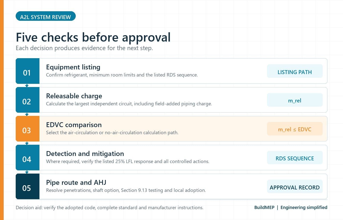
Do not start by asking whether every A2L system needs a wall sensor. Start with the equipment listing and installation instructions, determine the releasable charge of the largest independent circuit, calculate the effective dispersal volume charge (EDVC), and then verify the pipe-penetration or shaft route.
The often-repeated "4 lb exemption" is not a universal safe-harbor. In a specific ASHRAE Standard 15 human-comfort pathway, releasable charge above 4 lb triggers a listed refrigerant detection system under stated conditions. A smaller charge may avoid that particular trigger, but charge limits, minimum room size, the product listing and the adopted mechanical code still apply.
What the R-410A transition means for a project
The U.S. EPA Technology Transitions program limits many new residential and light-commercial air-conditioning and heat-pump systems to a refrigerant GWP of 700 from January 1, 2025. Comfort-cooling chillers also use a 700 limit from that date. The current EPA sector table gives VRF systems an installation compliance date of January 1, 2027, subject to its stated exceptions and definitions.
That policy has accelerated the use of lower-GWP options such as R-32 and R-454B, both classified A2L. It does not mean that these are the only refrigerants used by every manufacturer or in every chiller, VRF or DX product. It also does not ban service of existing R-410A equipment.
| Question | Practical answer | Design consequence |
|---|---|---|
| Is this new equipment or an existing installation? | EPA restrictions primarily address new products and systems by sector and compliance date. | Existing R-410A systems can still be serviced. Check EPA labeling and service-component provisions. |
| Can R-32 or R-454B be charged into an R-410A unit? | No, unless that exact conversion is covered by the equipment manufacturer and listing. | Pressure, oil, controls, charge limits and ignition-risk provisions differ. Never treat A2L refrigerant as a drop-in retrofit. |
| Is the project date alone enough? | No. Sector, product/system status, manufacture/import date and listed exceptions matter. | Use the current EPA sector table, not a generic phase-down graphic. |
For operating-pressure context and refrigerant comparisons, see BuildMEP's HVAC refrigerant pressure and pressure-switch guide.
A2L: what the classification says
Under ASHRAE Standard 34, the letter A identifies the lower-toxicity class and 2L identifies lower flammability with a maximum burning velocity of 10 cm/s. That is different from A1 refrigerants, which do not propagate a flame under the classification test, and A3 refrigerants, which have higher flammability.
"Lower flammability" does not mean "nonflammable." Safe application depends on limiting the concentration that a credible leak can create and, where required, using listed detection and mitigation to disperse the release and control ignition sources.
Keep the three compliance paths separate
1. Listed equipment
UL 60335-2-40 evaluates air-conditioning and heat-pump equipment, including refrigerant detection system (RDS) functions where the listing requires them.
2. System and occupied space
ASHRAE Standard 15 addresses the installed refrigeration system, releasable charge, EDVC, connected spaces, air circulation and mitigation.
3. Building route
The adopted mechanical and building codes govern penetrations, rated assemblies and shaft construction. ASHRAE 15 addenda change how a shaft may be treated.
A UL-listed indoor unit does not automatically prove that the total installed circuit charge is acceptable for every connected room. Likewise, an ASHRAE charge calculation does not authorize changing the sensor, fan sequence or valve arrangement of listed equipment.
OEL, 25% LFL and trouble are not one alarm ladder
The original design context determines the threshold. The occupational exposure limit (OEL) and 25% of the lower flammability limit (LFL) address different applications; they should not be described as two universal stages of the same detector alarm.
| Signal or threshold | Where it appears | What it means for design |
|---|---|---|
| 25% LFL | Listed-equipment and occupied-space A2L mitigation path | The RDS initiates the required response before concentration approaches the refrigerant's LFL. The absolute concentration is refrigerant-specific. |
| OEL | Applications such as detector-initiated ventilation of an A2L/B2L pipe shaft under ASHRAE 15-2024 Addendum b | The applicable provision may limit the detector setpoint to the OEL. This is not automatically a pre-alarm for a 25% LFL event. |
| Trouble alarm | RDS self-diagnostic failure | A failed self-check is the trouble condition; required fail-safe mitigation is also initiated. OEL itself should not be mislabeled as "trouble." |
The response chain: signal first, mitigation second
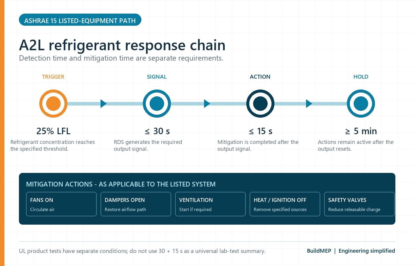
For the ASHRAE Standard 15 listed-equipment pathway, the RDS generates an output within 30 seconds when exposed to 25% LFL within the specified tolerance. The required mitigation actions are then completed within 15 seconds after that output and maintained for the required period after reset.
- Detect and signal. The factory-set RDS identifies the refrigerant concentration and provides its output within the allowed detection interval.
- Execute the listed sequence. Depending on the application, the response can energize circulation fans, open zone dampers, start required mechanical ventilation, de-energize duct heaters or ignition sources, and operate safety shutoff valves.
- Hold and verify. The sequence remains active for the required post-reset period. Commissioning verifies the actual fan, damper, valve and shutdown actions, not merely a BMS graphic.
EDVC: calculate the applicable path, not room volume × RCL
EDVC is the maximum releasable refrigerant charge permitted by the applicable dispersal-volume calculation. The compliance comparison is:
mrel is the releasable charge determined under the standard for the system arrangement. For a single independent circuit it will often be that circuit's charge, including field-added piping charge. For multi-circuit equipment or systems with listed safety shutoff valves, the determination must follow the relevant provisions and manufacturer documentation.
Path A: qualifying air circulation (2022-edition reference example)
Trane’s cited bulletin uses ASHRAE Standard 15-2022. For its qualifying continuous or detector-initiated air-circulation pathway, the relationship is:
Use consistent units. ASHRAE Standard 34 commonly states LFL in lb/1000 ft³ or g/m³; convert it before multiplying by Veff. The occupancy factor is 1.0 for noninstitutional occupancies and 0.5 for institutional occupancies in this path.
Path B: no qualifying air circulation
For a system that does not qualify for the air-circulation path, the standard uses its tabulated default-charge method and refrigerant conversion factor:
Mdef comes from the applicable ASHRAE Standard 15 table based on the space and release-height conditions. FLFL adjusts that value for the selected A2L refrigerant. Do not reconstruct the table from memory or substitute gross room volume.
Illustrative screening calculation using Trane’s 2022-edition method
Assume a noninstitutional office system has a confirmed effective dispersal volume of 10,000 ft³. It uses R-454B with an LFL of 18.5 lb/1000 ft³, or 0.0185 lb/ft³, based on the cited manufacturer application example. The largest independent circuit has a releasable charge of 18 lb and the listed system provides qualifying detector-initiated air circulation.
The 10,000 ft³ and 18 lb inputs above are illustrative assumptions, not the dimensions or charge of Trane’s worked project. Trane’s December 2023 bulletin explicitly uses ASHRAE Standard 15-2022; it is not proof of compliance with Standard 15-2024 or a project’s adopted edition. This example demonstrates the workflow, not a universal selection. Confirm the current ASHRAE Standard 34 LFL, the adopted Standard 15 edition/addenda and all product-listing conditions for the actual refrigerant and equipment.
Pipe shafts: what Addenda a and b actually changed
ASHRAE Standard 15-2024 Addendum a introduced a shaft alternative for continuous refrigerant pipe or tube, including joints and connections, tested in accordance with Section 9.13. The provision should not be summarized as "no mechanical joints." The integrity test, pipe route and adopted code are the controlling items.
Addendum b, approved March 31, 2026, supersedes the earlier shaft language and brings the standard closer to model building-code treatment. It makes protection and approved sealing of penetrations the primary route and permits a fire-resistance-rated shaft as an option where applicable. If a shaft is used for A2L or B2L piping, Addendum b addresses natural or mechanical ventilation and gives exceptions.
| Route or condition | Design review | Evidence to retain |
|---|---|---|
| Pipe penetrates walls, floors or ceilings | Seal the annular space using an approved, compatible system; protect rated assemblies under the building code. | Penetration detail, product data, firestop system where applicable and inspection record. |
| Continuous pipe/tube, including joints and connections, tested per Section 9.13 | May qualify for the no-shaft alternative. | Pressure-test procedure, readings, limits, witness/acceptance and project-specific AHJ approval. |
| A fire-resistance-rated A2L/B2L pipe shaft is used | Check natural or mechanical ventilation unless an Addendum b exception applies. | Shaft section, airflow/opening calculation, discharge location, detector basis and controls sequence. |
| Detector-initiated mechanical shaft ventilation | Setpoint must not exceed the refrigerant OEL; locate the detector or sample point where leaked refrigerant will concentrate. | Sensor listing/data, setpoint, location rationale, fan proof and commissioning results. |
Detector location and BMS integration
"A2L vapor is heavier than air, so mount every detector 12 inches above the floor" is too broad. Airflow, enclosure geometry, leak source, operating state and the product listing determine where refrigerant will reach the sensing element.
- Ducted systems: in the cited ASHRAE pathway, the detector is located within the listed equipment.
- Directly connected, nonducted systems: the same pathway permits the detector in the equipment or in the occupied space not more than 12 in. (30 cm) above the floor, within 3.3 ft (1 m) horizontally and with direct line of sight to the unit.
- Pipe shafts and machinery spaces: follow the specific provision, refrigerant behavior, airflow and approved detector instructions. The occupied-space dimensions above are not a universal placement rule.
A factory RDS evaluated with listed equipment and an independent field gas detector are not automatically interchangeable. The required safety response must remain within the listed/approved control architecture. BACnet monitoring can provide status, alarm and maintenance visibility, but a BMS point should not replace the required local fail-safe sequence unless the listing and approved design expressly allow it.
Common failure modes
| Failure | Why it fails | Better verification |
|---|---|---|
| Using total project charge for every room | EDVC is compared with the applicable releasable charge, normally evaluated by independent circuit and approved isolation arrangement. | Build a circuit charge ledger including factory charge, field piping and valve boundaries. |
| Using room volume × RCL as EDVC | It ignores the applicable Standard 15 A2L formula, release height, connected spaces, concentration factor and occupancy factor. | Document whether the air-circulation or no-air-circulation path applies. |
| Calling OEL a trouble alarm | OEL may be a ventilation setpoint; trouble is associated with detector self-diagnostic failure. | Write a cause-and-effect matrix with each initiating condition and response. |
| Assuming all charges below 4 lb need no review | The 4 lb value belongs to a particular RDS trigger, not every charge-limit and listing requirement. | Check minimum room size, EDVC, listing and adopted code even when no RDS is triggered. |
| Removing the shaft because there are no brazed joints | The current provision is based on the route, tested pipe/tube including joints and connections, penetrations and adopted code. | Submit the Section 9.13 test basis and penetration/firestop details to the AHJ. |
| Testing only the sensor input | A changing BMS value does not prove fan airflow, damper position, heater shutdown, valve closure or fail-safe behavior. | Functional-test the complete sequence and retain measured results. |
Design and submittal checklist
- Adopted mechanical/building code and ASHRAE edition/addenda recorded
- Refrigerant designation and safety class confirmed
- Equipment listing and installation manual obtained
- Largest independent-circuit charge calculated
- Field-added piping charge included
- Safety shutoff valve boundaries verified as listed/approved
- mrel stated separately from total project charge
- Veff and connected spaces documented
- EDVC path and units shown
- Minimum room area/volume checked
- RDS model, refrigerant and listing matched
- Cause-and-effect sequence issued
- Detector location justified from the applicable clause and manual
- Shaft/penetration route resolved with the AHJ
- Pressure test and firestop records included
- Complete mitigation sequence functionally tested
Frequently asked questions
Does every R-454B split system require a separate wall detector?
No. Many systems use an RDS evaluated as part of the listed equipment. Whether detection is required, and where it is located, depends on releasable charge, system arrangement, room/connected-space conditions, equipment listing and adopted code.
Does an A2L detector always alarm at the OEL first?
No. The OEL and 25% LFL appear in different applications. For example, Addendum b uses an OEL-limited setpoint for detector-initiated A2L/B2L shaft ventilation, while the listed occupied-space mitigation path uses 25% LFL. A trouble alarm relates to RDS diagnostic failure.
Can the BMS perform the required mitigation?
Only if the approved listing, equipment instructions and code path permit that architecture. A BMS is normally valuable for supervision and recording, but the safety sequence must not depend on an unlisted network path or general-purpose software when the required response is integral to listed equipment.
Can an existing R-410A system be converted to R-32 or R-454B?
Do not treat either refrigerant as a drop-in replacement. Use only equipment designed, marked and listed for that refrigerant, following the manufacturer's approved instructions.
Is a rated refrigerant pipe shaft always required in a high-rise?
No universal answer applies. Addendum b focuses on approved penetration protection and permits shafts, while tested continuous pipe/tube may qualify for an alternative. The adopted building and mechanical codes and the AHJ determine the project requirement.
Primary references and verification trail
- U.S. EPA: Technology Transitions HFC restrictions by sector — current GWP limits, compliance dates and sector notes.
- U.S. EPA: Frequent questions on the HFC phasedown — application to new equipment and treatment of existing systems.
- ASHRAE Standard 15-2024 Addendum a — tested continuous pipe/tube and shaft alternative.
- ASHRAE Standard 15-2024 Addendum b — penetration, shaft and ventilation provisions; approved March 31, 2026.
- ASHRAE Standard 15-2019 Addendum s — source history for A2L RDS output, mitigation timing, placement and self-diagnostic provisions carried into later editions.
- UL Solutions: Updated refrigerant detection system requirements — UL 60335-2-40 fourth-edition Annex LL and 25% LFL product response.
- Trane: ASHRAE Standard 15-2022 A2L EDVC single-zone example — manufacturer application example used to cross-check units and the worked calculation.
Review date: August 2026. Purchase or access the complete adopted standards for compliance work; the linked addenda and application material do not replace the full documents.