Part of Duct Design & Fabrication: The Complete BuildMEP Guide →
BuildMEP HVAC measurement guide
This guide walks through the difference between static, velocity, and total pressure, how to measure total external static pressure (TESP) across packaged HVAC equipment, and how to turn that reading into a diagnosis you can actually defend. It's written for low-pressure air systems — but the equipment manufacturer's measurement boundary and performance data always have the final word.
Decision brief
Static pressure is a pressure at a single point — it isn't another word for system resistance. Resistance is what causes a pressure loss once air is actually moving. To check equipment in the field, measure the return and supply static pressures at the points the manufacturer defines, work out TESP algebraically, and check that number against the exact unit's blower table for the mode it's running in.
Four things can change the conclusion:
- the equipment boundary the manufacturer used;
- fan speed, airflow-control mode, and operating stage;
- which components sit inside or outside that boundary; and
- how good the pressure measurements are, and where they were taken.
Static, velocity, and total pressure aren't the same thing
Inside a duct, static pressure is the pressure air exerts perpendicular to the direction of flow, and it's usually reported relative to the surrounding atmosphere. A return duct typically runs below room pressure, so its gauge static pressure reads negative. A supply duct downstream of the fan typically runs above room pressure, so its reading is positive.
Velocity pressure is the kinetic energy of the moving air. Total pressure is the sum of both:
Friction, filters, coils, fittings, dampers, grilles, and everything else in the airstream create total-pressure losses as air moves through them. Where the duct area stays constant, a measured static-pressure drop is usually a decent stand-in for the component's actual pressure loss, since velocity pressure barely changes there. But across a transition, a branch, a fan, or any other change in area, static pressure by itself can mislead you — energy can shift back and forth between static and velocity pressure.
ESP, TESP, or fan pressure — which one should you compare?
| Term | What it describes | Where it is used | Key caution |
|---|---|---|---|
| Static pressure, Ps | Gauge pressure at one point in the airstream. | Duct sensors, field profiles, duct construction pressure class. | Not airflow, and not resistance by itself. |
| External static pressure, ESP | A static-pressure requirement assigned outside a stated equipment or fan boundary. | Equipment schedules, selection data, and system design. | "External" only means something once you know what the manufacturer counted as "inside" the rated product. |
| Total external static pressure, TESP | The static-pressure difference between the equipment's external outlet and inlet measurement points. | Field checks of furnaces, fan coils, air handlers, and packaged units. | Use the manufacturer's tap locations and blower table — filters and coils can fall inside or outside the rated boundary depending on the unit. |
| Fan static or fan total pressure | A fan-rating quantity defined at specified inlet and outlet planes. | Standalone fan curves and fan-selection software. | Curves can be built on either static or total pressure — check the axis label and rating definition rather than assuming it's ESP. |
Field reality: where the cabinet boundary sits changes the answer
A filter sitting in a return grille is outside most air-handler cabinets. A filter in a factory filter rack, though, might be part of the tested product configuration — or it might be listed as an accessory with its own separate pressure-drop allowance. The same ambiguity shows up with add-on coils, economizers, heat-recovery sections, plenums, and sound attenuators. Mark the real measurement points on the unit drawing before you start comparing numbers.
How to measure TESP across HVAC equipment
Measurement workflow
- Identify the comparison. Pull the exact model's installation and service data, then find the blower-performance table, rated external pressure, included components, fan speed or control mode, and the prescribed tap locations.
- Make the work safe. Kill power before you drill anything. Check that nothing — no coil, heat exchanger, drain pan, wiring, refrigerant circuit, or rotating part — sits behind where you plan to put the port. Use factory ports if the unit already has them.
- Stabilize the operating condition. Restore power, close the panels, set a clean or otherwise known filter condition, open the dampers and terminals you intend to test, and run the relevant heating, cooling, ventilation, or full-flow stage until it settles. Record the fan command or speed.
- Zero and connect the instrument. Use a manometer with a suitable range and resolution. Reference every static-pressure reading to the same ambient space, or connect the probes differentially if that's what the manufacturer's method calls for.
- Measure representative static pressure. Orient the probes or taps correctly, and stay away from obvious turbulence and system-effect zones. If you can't find one stable, representative plane, use multiple points or a recognized test-and-balance procedure — don't just drill one convenient hole and call it done.
- Calculate algebraically. In the common case of a negative return reading and a positive supply reading, subtracting the negative value effectively adds the two magnitudes together.
- Measure airflow independently. Use a proper traverse, flow station, hood, or manufacturer-approved method. Static pressure alone can't tell you what the airflow actually is.
- Compare like with like. Pull the table or curve for the exact same model, airflow-control setting, speed, motor, voltage/frequency, accessories, and operating stage. Note your uncertainty, and repeat any reading that looked unstable.
- Seal and label the ports. Close the test holes with approved plugs and record where they are, so future trend data uses the same measurement boundary.
Units: 1 in. w.c. is roughly 249 Pa. Report only as much precision as your instrument actually supports — hundredths of an inch water column are typical for low-pressure HVAC service work.
Worked case: a high TESP reading with low airflow
Assumed example: A technician is checking a constant-speed packaged unit that's supposed to deliver 1,200 cfm. The manufacturer's table for this exact model shows 1,200 cfm at 0.50 in. w.c. TESP, for the selected speed and installed configuration. That number is just an example input, not a universal limit.
| Item | Value | Interpretation |
|---|---|---|
| Return static pressure | −0.22 in. w.c. | The suction-side gauge pressure at the defined external inlet plane. |
| Supply static pressure | +0.38 in. w.c. | The discharge-side gauge pressure at the defined external outlet plane. |
| Calculated TESP | 0.38 − (−0.22) = 0.60 in. w.c. | 0.10 in. w.c. — about 20% — above the example table point. |
| Independent airflow test | 1,020 cfm | 15% below the 1,200 cfm target in the example; pressure and airflow are now telling the same story. |
| Component profile | Filter drop 0.24 in. w.c.; clean baseline 0.10 in. w.c. | The filter alone accounts for 0.14 in. w.c. of extra loss compared with the recorded clean baseline. |
If the filter doesn't fully explain what you're seeing, keep working section by section: return grille and duct, filter, coil, dampers, supply duct, terminals, and any accessories. A package-unit maintenance check should pair these airside measurements with belt, coil, motor-current, and control-condition evidence.
Read pressure alongside airflow and fan type
A "high static" reading doesn't trigger one universal motor response. The operating point is wherever the fan curve and the system curve cross, and the motor or control strategy in use matters a lot:
- Constant-speed or permanent-split-capacitor blowers: more resistance usually means less airflow. Motor power doesn't necessarily go up, so "the motor always works harder" isn't a rule you can count on.
- Constant-airflow electronically commutated motors: the control can ramp up speed and power to hold airflow steady, right up until it hits its programmed or physical limit. Noise and energy use often climb before airflow actually drops.
- VFD-controlled commercial systems: the controller may speed up the fan to hold a duct-static setpoint. Trend fan speed, terminal-damper positions, airflow, and pressure together, not one in isolation.
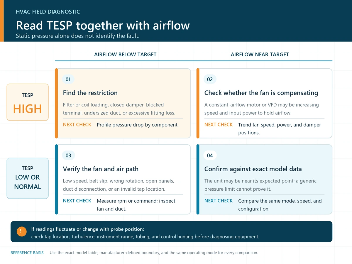
Low TESP needs context too. It could mean low fan speed, a slipping belt, open access panels, disconnected or leaking ductwork, a poorly placed probe, wide-open bypass paths, or just a genuinely low-resistance system. On some constant-speed fans, lower resistance can actually push airflow and noise too high. The number by itself won't tell you which one it is.
Use a pressure profile to find the restriction
TESP tells you the total load across the equipment boundary you selected. The differential pressure across individual components tells you where that pressure is actually being lost. Record both sides of each suspect component at the same airflow, then compare against a clean baseline, design schedule, or manufacturer data.
| Observed pattern | Possible causes | Next verification |
|---|---|---|
| TESP high; airflow low | Dirty filter/coil, closed damper, undersized duct, blocked terminal, excessive fitting loss. | Profile the pressure drop by component, check damper positions, and compare airflow against the exact blower table. |
| TESP low; airflow low | Low fan speed, belt slip, wrong rotation, failed wheel, open cabinet, duct disconnection/leakage, measurement error. | Measure fan rpm/command and motor data, inspect the fan and duct, and repeat the pressure readings at valid planes. |
| TESP high; airflow near target | Constant-airflow motor or VFD is compensating; developing restriction; setpoint higher than necessary. | Trend fan speed and input power, profile the components, and verify the control sequence and terminal-damper positions. |
| Reading fluctuates or changes with probe position | Turbulence, swirl, poor tap location, pulsating fan/control, inadequate instrument damping. | Relocate or average the taps using a recognized method, and check the instrument's range and tubing. |
Trend the right variable
For filter maintenance, trend the differential pressure across the filter at a comparable airflow, not just the whole-unit TESP. A variable-speed fan can hold airflow steady even as the filter's pressure drop climbs, and other changes in the system can push TESP the opposite direction at the same time. Record airflow or fan speed alongside every trend point.
How duct sizing affects available pressure
For a fixed airflow, shrinking the duct area raises velocity. Velocity pressure scales roughly with the square of velocity, and straight-duct friction plus fitting losses generally climb sharply as velocity goes up. That leaves the fan with less pressure available for filters, coils, terminals, and balancing devices.
Preliminary tools like the BuildMEP Duct Size Calculator are useful for checking area, velocity, and approximate straight-duct friction. A final design still needs fitting and component losses, system effect, leakage, acoustics, diversity/control modes, and the fan's published performance basis. The same pressure concepts apply to exhaust applications, but you still have to check the duty point against the actual exhaust-fan curve; see the exhaust fan selection guide.
Common mistakes and their corrections
| Mistake | Consequence | Field symptom | Correction |
|---|---|---|---|
| Calling static pressure "resistance" | Pressure readings get treated as a cause instead of as evidence. | Parts get replaced without ever locating the actual pressure loss. | Use component pressure drops and airflow together to locate the resistance. |
| Adding signed readings incorrectly | TESP comes out understated or with the wrong sign. | −0.22 and +0.38 are reported as 0.16 instead of 0.60 in. w.c. | Subtract inlet from outlet algebraically, sign and all. |
| Assuming every fan curve is an ESP curve | The system duty point and the fan rating end up using different pressure definitions. | The selected fan misses its airflow target despite looking like it matches the schedule. | Check whether the curve is reporting fan static pressure, fan total pressure, or equipment TESP. |
| Using one tap in disturbed flow | The reading doesn't actually represent that duct plane. | Pressure changes materially when the probe moves a few centimetres. | Use valid straight sections, multiple points, or a recognized test-and-balance method. |
| Comparing different operating modes | Trend data looks like a restriction when it's really just a speed or damper change. | TESP shifts between visits with no matching component evidence. | Record mode, stage, fan command, damper state, filter condition, and airflow. |
| Using a generic 0.50 in. w.c. limit | Good equipment gets rejected — or an overloaded unit gets signed off. | The field result gets judged without ever pulling the exact-model blower table. | Use the manufacturer's data for the installed model and configuration. |
Verification handoff
- Confirm the exact equipment model, fan/motor option, supply frequency, installed accessories, and rated measurement boundary.
- Record operating mode, fan speed or command, filter condition, damper/terminal state, and open/closed panel condition.
- Measure inlet and outlet static pressure with a zeroed, suitable-range instrument at valid locations.
- Calculate TESP algebraically and retain the signed raw readings.
- Measure airflow independently and document the method and uncertainty.
- Compare the result with the exact manufacturer table or curve on the same pressure basis.
- Profile suspect filters, coils, dampers, and duct sections at a comparable airflow.
- Correct the identified cause, then repeat pressure and airflow checks under the same condition.
- Seal test ports and preserve the baseline for future trend comparison.
Evidence trail and applicability
- ASHRAE Handbook—Fundamentals, Chapter 21: Duct Design (2021) — pressure relationships, total-pressure loss, duct design, and measurement fundamentals.
- ANSI/ASHRAE Standard 41.2-2026 and Standard 41.3-2025 scopes — recognized methods for airflow/velocity and pressure measurements. Apply the full standards where contractual test accuracy is required.
- AMCA: Straightening Out Fan Curves (2020) — distinction between fan static-pressure and total-pressure curves.
- AMCA Publication 203-90 (R2011): Field Performance Measurement of Fan Systems — scope for field fan-system measurements. Use the current project-specified edition or method.
- U.S. Department of Energy: Furnace Fan System Curve Derivation (2012) — equipment external-static-pressure boundary and field ESP concept.
Last technical review: 29 August 2026. This guide covers general HVAC measurement and diagnostic principles. The actual work is governed by project specifications, adopted standards, safety procedures, manufacturer instructions, and the authority having jurisdiction.
Frequently asked questions
What is a normal HVAC static pressure?
There isn't one universal "normal" value. Residential equipment often gets tested around familiar figures like 0.50 in. w.c., but that's not an automatic pass/fail threshold. Use the exact model's blower-performance data and its defined equipment boundary instead.
Can static pressure tell me airflow?
Not on its own. A manufacturer's blower table can relate airflow to TESP for a specific unit, speed, and configuration, but installation effects and control modes can shift performance from there. For commissioning or diagnosis, verify airflow independently rather than inferring it.
Why are return static-pressure readings negative?
The return duct, upstream of the fan, usually sits below the room's atmospheric pressure around it. A gauge referenced to that room will show a negative value as a result. That negative reading doesn't mean negative velocity pressure, and it doesn't mean the air is flowing backward.
Should filter differential pressure equal whole-unit TESP?
No. Filter differential pressure is the drop across just one component. TESP spans the whole external equipment boundary and picks up the combined effect of every external component between its inlet and outlet measurement planes.
Related BuildMEP resources
Part of a BuildMEP guide
This article is one step in Duct Design & Fabrication: The Complete BuildMEP Guide. It puts static pressure, fitting geometry and on-site fabrication in the order you actually deal with them on a project.