A frequently asked question on the internet is how to replace BTU meters. It seems like replacing the BTU meter is a simple bolt-in / bolt-out task. It is, until the new meter begins to count energy in numbers no one can believe. You’re then back at site at midnight figuring out if it’s the meter, the sensors, the pipework it’s in, or how it was commissioned.
It shows a real replacement: two ultrasonic BTU meters (DN65 and DN80) with five thermowells on chilled water supply and return lines to AHUs, achieved on night shift for a facility management team. It includes steps taken in the sequence and technical details that determine whether or not the meter reads correctly afterwards. A template for a method statement is enclosed at the end that can be downloaded.
What a BTU Meter Actually Measures
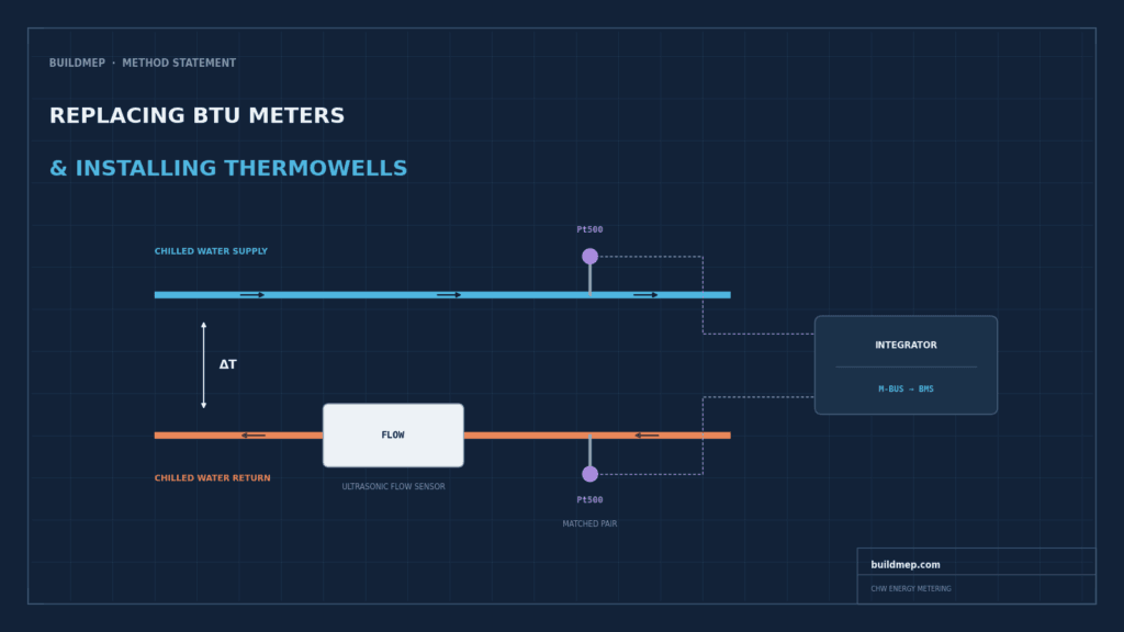
A thermal energy meter (also referred to as a BTU meter, a heat meter or a cooling meter, depending on the sources) does not measure energy. It measures 3 things, and calculates the fourth:
- Volumetric flow rate through the pipe
- Supply temperature
- Return temperature
Of these, the integrator calculates the thermal energy for the fluid based on the measured condition, its density and specific heat capacity. In simple terms: energy is the product of flow times the difference between hot and cool water, times fluid’s heat carrying capacity.
This structure has one implication that it is worth contemplating before you pick up a spanner. Two of the measured inputs are temperatures, and it is the difference between the two temperatures that counts for the calculation. Not their absolute values. The difference.
Why Chilled Water Metering Is Harder Than Heating
That’s what gets people confused. Heating circuits may have a 20 K temperature difference between flow and return. Usually a chilled water system used for AHUs will operate at around 6 °C supply and 12 °C return, therefore a ΔT of approximately 6 K. Others are tighter than this.
Now take into sensor error. Under EN 1434, the standard harmonised to the MID that governs heat meter requirements, a Class 3 matched temperature sensor pair is permitted a maximum error of 3.5% at its minimum rated temperature difference, which for a 3 K ΔTmin works out to roughly 0.105 K in absolute terms. That’s a very small number. But watch what it does across different operating conditions:
| Operating ΔT | Pair error (0.105 K absolute) | Resulting energy error |
|---|---|---|
| 20 K (typical heating) | 0.105 K | ~0.5% |
| 10 K | 0.105 K | ~1.1% |
| 6 K (typical CHW) | 0.105 K | ~1.8% |
| 3 K (low-ΔT operation) | 0.105 K | ~3.5% |
Same sensors, same meter, same installation quality. The only thing that changed is the temperature difference the system happens to be running at. If the building suffers from low delta-T syndrome, and plenty do, the metering error grows exactly when you most need reliable data to diagnose it.
This is why matched sensor pairs matter so much on chilled water. The two sensors are tested together at multiple temperatures and supplied as a calibrated pair specifically so their errors track each other rather than compounding. Never mix sensors from different pairs, and never replace just one half of a pair.
Before the Shutdown: Checks Worth Doing
Confirm the straight-run available
To accurately measure flow using ultrasonic meters, there must be a fully developed flow profile and a settled flow. The general manufacturer guideline is 10 pipe diameters upstream and 5 pipe diameters downstream but this can vary depending on the model, and may be higher if the flow is seriously disturbed. Upstream requirement can be increased to 15D or 20D due to two elbows in different planes, or a control valve, or a pump close upstream.
When replacing like-for-like in an existing position, measure the existing item, don’t assume the installation was right the first time. Where space permitted, lots of legacy meters were installed. If space truly is not available, the standard compromise is the two-thirds rule: distribute two-thirds of the available straight pipe to the up stream side and one third to the down stream side, and be happy with the compromise.
Straight-run and turndown are really the same sizing question asked at two different points in a meter’s life — one at selection time, one at installation time. If you’re specifying a new meter rather than replacing this one like-for-like, our chilled water BTU meter sizing guide covers the flow-turndown and matched-sensor decisions that come before this installation stage.
Plan thermowell positions relative to the meter
This one gets missed routinely. A thermowell protruding into the pipe is itself a flow obstruction, in the same category as an elbow or a reducer. Put one immediately upstream of an ultrasonic meter and you’ve introduced a disturbance into the very flow profile the meter depends on.
Standard practice is to locate the temperature sensor downstream of the flow sensor, or far enough upstream to sit outside the meter’s straight-run requirement. Check the meter’s installation manual, because manufacturers are specific about this and the requirement differs between models.
Confirm approval scope if the data is used for billing
Worth verifying rather than assuming. MID approval under Annex MI-004 covers heat metering. Cooling-energy measurement has historically sat outside that scope and is typically covered by separate national approvals. If the meter output feeds tenant billing or cost allocation rather than just monitoring, confirm what your specific meter is actually approved to measure.
How to Replace BTU Meters: The Full Sequence
1. Night shift planning and permits
All works were scheduled overnight, both to avoid summer heat and to keep the AHUs off the occupied-hours critical path. Hot work permits were in place for the socket welding, along with work-at-height permits where scaffold access was needed. Temporary lighting was set up before anything else started.
2. Isolation and draining
The FM team coordinated isolation and drain-down of the affected chilled water sections. Nothing gets loosened until isolation is confirmed and verified, not just requested.
3. Removing the existing meters
Flange bolts loosened, sensor cables disconnected and labelled, meters removed and set aside. Labelling matters more than it seems: supply and return sensor cables look identical once they’re off the integrator, and getting them reversed on reinstatement produces a meter that reads negative energy or nothing at all.
4. Installing the new meters
New meters positioned with attention to flow direction (there’s an arrow on the body, and it is not decorative), flange faces aligned, new gaskets fitted, and bolts tightened to the manufacturer’s torque figure in a proper crossing pattern. Over-torquing a flange to stop a weep is how you crack a meter body.
5. Thermowell installation
Positions marked, holes drilled, threaded sockets welded, thermowells fitted and tightened. Two details decide whether these read accurately:
- Insertion depth. The sensor tip needs to sit well into the flow stream, not hovering near the pipe wall where it reads a boundary layer temperature rather than bulk fluid temperature. Aim for the tip around the pipe centreline.
- Orientation. On horizontal runs, avoid pointing the well straight down into the bottom of the pipe where sediment collects.
It’s also worth knowing what a thermowell costs you in measurement terms. It buys you the ability to pull a sensor without draining the system, which on an occupied building is close to essential. In exchange, it slows the sensor’s response and introduces a small heat conduction error along the stem. Fitting the sensor properly into the well, fully bottomed out, minimizes both.
6. Sensor and cable connection
Paired Pt500 sensors inserted into the thermowells and wired back to each meter’s integrator. Pt500 elements change resistance roughly 1.925 Ω per K, against about 0.385 Ω per K for a Pt100, which makes lead resistance proportionally less significant. Even so, EN 1434 sets cable length limits above which four-wire connection becomes necessary. On a long run back to a plant room integrator, check this rather than assuming two-wire will do.
Route cables away from power cabling and secure them properly. A sensor cable that gets snagged during future maintenance is a fault that will take somebody an hour to find.
7. Refill, pressurisation and leak test
Chilled water reintroduced slowly, with air vented as the system fills. Every flange, thermowell boss and welded socket checked under working pressure. Slow refilling is not just caution; filling fast traps air, and trapped air in an ultrasonic meter’s measuring section produces nonsense readings or a total loss of signal.
8. Commissioning and BMS integration
Meters powered up, local displays checked for sensible flow and temperature readings, then M-Bus communication verified back to the BMS. Things worth confirming at this stage rather than later:
- Supply and return sensors are reading the right way round, giving a positive ΔT in the expected direction
- Flow reading is plausible against known pump duty and system conditions
- Units and scaling on the BMS side match what the meter is actually transmitting
- Initial index readings are recorded and documented before handover
If you need to sanity-check meter output against expected load, our HVAC unit converter handles kW, TR and BTU/h conversions, and the heat load calculator gives you a rough expected duty for the space the AHU is serving.
9. Insulation and vapour sealing
All disturbed pipework, meter bodies and thermowell bosses reinsulated, with vapour seal tape and cladding reinstated. On chilled water this is not cosmetic. Any break in the vapour barrier lets warm humid air reach a cold surface, and you get persistent condensation, dripping, corrosion under insulation, and eventually a call-out for a leak that isn’t a leak.
What Tends to Go Wrong
- Sensors swapped between supply and return, producing negative or zero energy accumulation
- Half a matched pair replaced with a spare sensor, quietly destroying pair accuracy
- Thermowell inserted too shallow, reading wall temperature instead of fluid temperature
- Insufficient straight run, or a thermowell placed immediately upstream of the meter
- Air not fully vented, giving unstable or absent ultrasonic signal
- Vapour barrier not properly sealed after reinsulation
- Initial readings never recorded, leaving no baseline to validate against later
Most of these are commissioning-stage problems that stay invisible until someone questions a bill months later. Several belong to the same family as the errors in our guide to common HVAC design mistakes: individually small, collectively expensive.
Quality and Safety Controls
Documented on this project, and worth carrying into any similar job:
- PPE maintained throughout, with daily briefings before each shift
- Hot work and work-at-height permits issued and closed out
- Fire blanket and extinguisher present during socket welding
- Model numbers and orientation verified against approved submittals
- Flange torque and leak test signed off
- Inspection request raised for consultant and client sign-off before reinstatement
Download: BTU Meter and Thermowell Method Statement
The full method statement used on this project is available as a template, covering purpose, scope, responsibilities, equipment, procedure, and quality control sections ready to adapt to your own project details.
Download the BTU Meter and Thermowell Method Statement (PDF)
More documents like this are in our Method Statements library.
Frequently Asked Questions
What does a BTU meter actually measure?
Flow rate, supply temperature and return temperature. It calculates thermal energy from those three inputs using the fluid’s density and specific heat capacity. It never measures energy directly.
Why do BTU meters need matched sensor pairs?
Because the calculation depends on the difference between two temperatures, not their absolute values. Matched pairs are tested and supplied together so their individual errors track each other instead of adding up. Replacing one sensor of a pair with an unmatched spare undoes that.
Can I install a thermowell right next to the flow meter?
Not upstream of it, generally. A thermowell protrudes into the pipe and disturbs the flow profile the ultrasonic meter relies on. Fit it downstream, or far enough upstream to fall outside the meter’s stated straight-run requirement. The installation manual will specify.
How deep should a thermowell be inserted?
Deep enough that the sensor tip sits in the bulk fluid stream, typically around the pipe centreline. Too shallow and it reads the slower, thermally different boundary layer near the pipe wall rather than the actual water temperature.
Why is chilled water metering less accurate than heating metering?
Because chilled water systems run much smaller temperature differences. The same absolute sensor error represents a far larger percentage of a 6 K ΔT than of a 20 K ΔT, so measurement error is proportionally bigger on cooling even with identical equipment.
Do I need to drain the system to replace a temperature sensor?
Not if thermowells are fitted. That’s their main practical benefit: the well maintains system pressure integrity while the sensor is withdrawn, so sensors can be swapped or recalibrated without a shutdown.