Practical plumbing design guide
Size domestic water piping by probable fixture demand and a segment-by-segment pressure budget—not by adding fixture flow rates or applying a velocity rule alone. This guide follows the IPC Appendix E workflow and finishes with a checked Type L copper selection.
Decision brief
WSFU determines the design flow; pressure loss and velocity determine the pipe size. For every main, riser, and branch, total the applicable combined, cold, or hot Water Supply Fixture Units (WSFU), convert that load to probable peak demand, add continuous demands in gpm, then test trial pipe sizes against the available pressure and the selected material's velocity guidance.
The numeric examples and calculator use the 2024 IPC model-code tables. The code edition and local amendments adopted for the project govern.
Use this method for
- Domestic cold- and hot-water distribution
- Building services, mains, risers, and fixture branches
- Systems sized from probable intermittent fixture use
Do not use it for
- Hydronic heating or chilled-water loops with known flow
- Fire protection demand
- Process piping or continuous loads without adding their actual gpm
Why fixture count is not design flow
Domestic fixtures operate intermittently. If every faucet, shower, and flush valve were added at its full rated flow, the service and distribution piping would be sized for a coincidence that is extremely unlikely to occur. WSFU converts fixtures with different flow rates, operating durations, and frequencies of use into a common probable-demand load.
A WSFU is dimensionless; it is not one gallon per minute. The relationship between WSFU and gpm is nonlinear, so a straight multiplier is not valid. The approach traces to Roy B. Hunter's probability work for the National Bureau of Standards and remains embedded in plumbing design methods.
Field reality: three loads can exist at the same location
A fixture supplied with both hot and cold water has a combined WSFU value and separate hot and cold values. The branch values are not meant to add back to the combined value. Size a building main from the combined column, a cold branch from the cold column, and a hot branch from the hot column.
Selected WSFU values
| Fixture | Occupancy/control | Cold | Hot | Combined |
|---|---|---|---|---|
| Bathroom group | Private, flush tank | 2.7 | 1.5 | 3.6 |
| Bathroom group | Private, flushometer valve | 6.0 | 3.0 | 8.0 |
| Kitchen sink | Private, faucet | 1.0 | 1.0 | 1.4 |
| Lavatory | Private, faucet | 0.5 | 0.5 | 0.7 |
| Lavatory | Public, faucet | 1.5 | 1.5 | 2.0 |
| Shower head | Private, mixing valve | 1.0 | 1.0 | 1.4 |
| Urinal | Public, ¾-in. flushometer valve | 5.0 | — | 5.0 |
| Water closet | Private, flush tank | 2.2 | — | 2.2 |
| Water closet | Private, flushometer valve | 6.0 | — | 6.0 |
| Water closet | Public, flushometer valve | 10.0 | — | 10.0 |
Use the complete table in the code edition adopted for the project. For a fixture genuinely absent from that table, the IPC directs the designer to compare it with a listed fixture having similar flow characteristics.
Code-edition boundary
This page explains the method and provides a model-code example. It is not a substitute for the adopted plumbing code, local amendments, water-authority data, or manufacturer pressure-loss information. Modern low-flow buildings may also be eligible for an approved alternative demand method.
The segmented-loss workflow
- Divide the system into segments. Break at branches, major elevation changes, and changes in demand. Identify the hydraulically remote fixture path; it is not always the geometrically highest fixture.
- Build the fixture schedule. Assign each fixture's adopted-code cold, hot, and combined WSFU values. Work backward from the remote outlet so each segment carries only the downstream load.
- Convert WSFU to peak gpm. Use the demand table appropriate to a system predominantly serving flush tanks or flushometer valves. Add hose bibbs, irrigation, air-conditioning makeup, and other continuous demands as actual gpm after the WSFU conversion.
- Build the pressure budget. Start with the minimum pressure available at the source. Deduct the remote fixture's required residual pressure, elevation loss at 0.433 psi/ft of rise, meter and tap losses, and manufacturer losses for backflow preventers, filters, softeners, regulators, and other devices.
- Test a trial pipe size. Add developed pipe length and equivalent fitting/valve length. For CAD takeoffs, the BuildMEP Total Length AutoCAD LISP can total selected line and polyline lengths before fitting allowances are added. At each segment's gpm, determine friction loss using the correct inside diameter and the code chart or manufacturer data for that material.
- Verify, then select. Confirm total pressure loss remains within budget and velocity remains within the selected code, manufacturer, and project guidance. A short run with generous pressure can still exceed an acceptable velocity, so pressure alone is not a velocity check.
WSFU and peak-demand calculator
Enter common fixture quantities, then add verified WSFU for any fixtures not shown. Select the demand-table basis explicitly. The tool uses the next listed WSFU row rather than interpolation and rejects loads beyond the source table.
Calculator preview notice: The controls are visible, but JavaScript has not initialized. Open the published page in a browser that permits scripts. In WordPress, confirm that the calculator script is preserved or loaded as an enqueued site asset.
Additional verified loads
2024 IPC Table E103.3(3) values; conservative next-listed-row lookup. Hot demand uses the non-flushometer curve. Verify the adopted code and project fixture schedule.
For other design utilities, browse BuildMEP MEP tools and calculations.
Worked case: carry the calculation to a selected pipe
Consider a commercial restroom group supplied by new Type L copper. The example uses model-code and handbook values to demonstrate the workflow; the pressure losses and reserve below are stated assumptions, not project data.
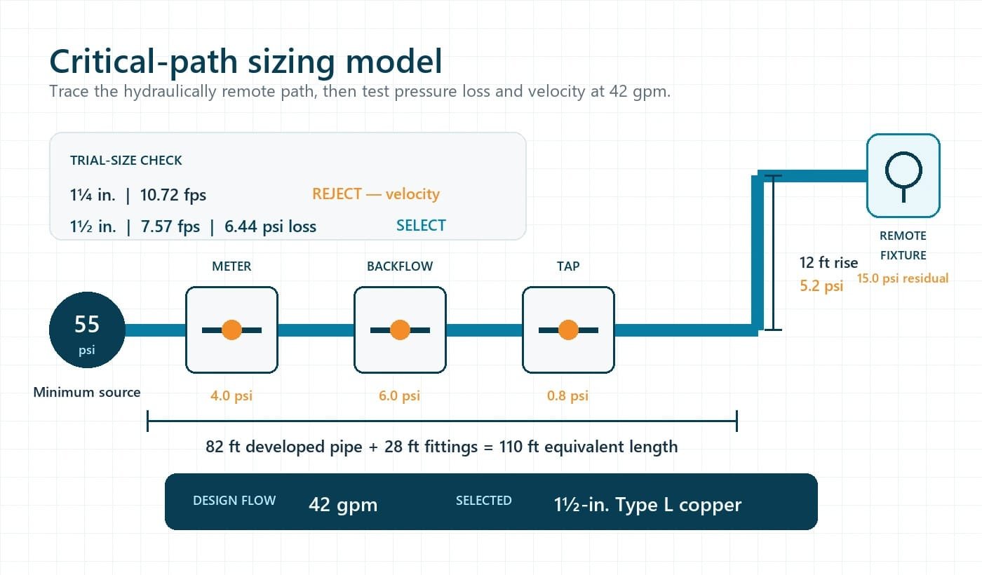
1. Fixture load
| Fixture | Quantity | Cold WSFU | Hot WSFU | Combined WSFU |
|---|---|---|---|---|
| Public lavatory, faucet | 2 | 3.0 | 3.0 | 4.0 |
| Public water closet, flushometer | 2 | 20.0 | 0 | 20.0 |
| Public urinal, ¾-in. flushometer | 1 | 5.0 | 0 | 5.0 |
| Totals | 28.0 | 3.0 | 29.0 | |
The system is predominantly flushometer supplied. Using the calculator's conservative next-listed-row method, 29 combined WSFU and 28 cold WSFU each use the 30-WSFU row: 42.0 gpm. The 3.0 hot WSFU uses the non-flushometer curve: 6.5 gpm.
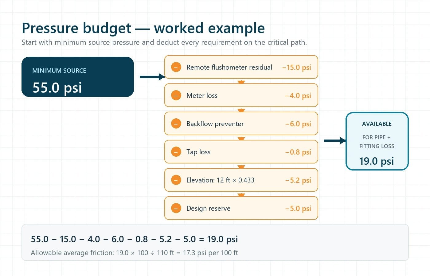
2. Pressure ledger for the critical cold-water path
Assumed minimum pressure at source: 55.0 psi
Deductions: 15.0 psi remote flushometer residual + 4.0 psi meter + 6.0 psi backflow preventer + 0.8 psi tap + (12 ft × 0.433 psi/ft) 5.2 psi elevation + 5.0 psi design reserve
Available for pipe and fitting friction: 55.0 − 15.0 − 4.0 − 6.0 − 0.8 − 5.2 − 5.0 = 19.0 psi
Equivalent critical-path length: 82 ft developed pipe + 28 ft fittings and valves = 110 ft
Allowable average friction: 19.0 psi × 100 / 110 ft = 17.3 psi per 100 ft
3. Trial Type L copper sizes at 42 gpm
| Nominal size | Inside diameter | Velocity | Friction | 110-ft loss | Decision |
|---|---|---|---|---|---|
| 1¼ in. | 1.265 in. | 10.72 fps | 13.65 psi/100 ft | 15.02 psi | Reject: velocity exceeds 8 fps |
| 1½ in. | 1.505 in. | 7.57 fps | 5.86 psi/100 ft | 6.44 psi | Passes example pressure and velocity checks |
| 2 in. | 1.985 in. | 4.35 fps | 1.52 psi/100 ft | 1.67 psi | Passes, but larger than required by these assumptions |
Example selection: 1½-in. Type L copper
The 1½-in. trial size loses about 6.44 psi through the equivalent run, below the 19.0-psi friction budget, and its calculated 7.57-fps velocity remains below the example's 8-fps ceiling. The 1¼-in. pipe fits the pressure budget but fails the velocity check, demonstrating why pressure loss cannot enforce velocity automatically.
The selected velocity is near the upper end of the Copper Development Association's 5–8 fps guidance. A quieter project criterion, aggressive water chemistry, a continuously circulating hot-water service, different fittings, or different manufacturer data could justify the 2-in. size.
Velocity is material- and application-specific
The IPC copper friction figures note that velocities above approximately 5–8 fps are not usually recommended, and the Copper Development Association applies the lower end to smaller copper sizes. Hot-water recirculation and aggressive water chemistry often require lower limits.
Do not publish or design from a single blanket limit for PEX, CPVC, steel, stainless steel, and copper. For pipe materials not covered by the IPC figures, use the adopted code plus the specific manufacturer's friction tables and velocity recommendations.
Failure-mode register
| Mistake | Consequence | Typical evidence | Correction |
|---|---|---|---|
| Using combined WSFU for a hot branch | Oversized hot-water piping and excess stored volume | Long wait time, greater heat loss, poor recirculation balance | Rebuild each segment from the hot column |
| Leaving a flushometer system on a tank demand curve | Peak demand is understated | Low residual pressure during flushing | Select the correct predominant-system basis |
| Ignoring continuous demand | Main or service is undersized during simultaneous operation | Pressure collapse during irrigation or equipment makeup | Add actual continuous gpm after WSFU conversion |
| Using static pressure without the low-pressure condition | Pressure budget is overstated | Complaints occur only at peak utility demand | Obtain the minimum available pressure from the authority and verify project conditions |
| Checking friction but not velocity | Noise, water hammer, or material damage risk | Flow noise and repeated transient events | Apply code, manufacturer, and project velocity criteria separately |
| Using nominal diameter in the hydraulic calculation | Velocity and friction are understated | Installed system performs worse than calculation | Use the actual inside diameter for material and pipe type |
Design verification handoff
- Confirm the adopted plumbing code edition and local amendments.
- Record cold, hot, and combined WSFU by pipe segment—not only by room or floor.
- Confirm whether flush tanks or flushometer valves predominate for each applicable system.
- Add every continuous demand as actual gpm after the demand-table conversion.
- Obtain minimum source pressure and manufacturer pressure losses at the design flow.
- Measure the hydraulically remote path and add equivalent fitting and valve length.
- Compare each trial size against friction, residual pressure, velocity, minimum branch size, and manufacturer requirements.
- Document assumptions, reserve, selected size, and the condition that controls the selection in the design note, submittal, or compliance matrix.
Standards and evidence trail
- International Code Council, 2024 IPC Appendix E—WSFU values, demand conversion, segmented-loss method, pressure components, example, and copper friction figures.
- International Code Council, 2024 IPC Chapter 6—fixture residual pressure and distribution requirements.
- Copper Development Association, Copper Tube Handbook, CDA A4015-24/23—Type L inside diameters, Hazen–Williams basis, friction data, and copper velocity guidance.
- National Institute of Standards and Technology, Roy B. Hunter, 1940—historical probability basis for estimating plumbing demand.
- NIST plumbing research overview—limitations of applying the original Hunter method to modern low-flow buildings.
Focused questions
Is WSFU the same as drainage fixture units?
No. WSFU estimates supply-side demand; drainage fixture units estimate discharge loading. They use different tables and cannot be exchanged.
Should I interpolate between WSFU rows?
This calculator deliberately uses the next listed row as a transparent conservative rule. If the adopted code, approved design procedure, or authority permits interpolation, document that method and its rounding behavior rather than embedding it silently.
Does the calculator select a pipe size?
No. It converts fixture load to demand. Final size still depends on the critical path's available pressure, elevation, devices, equivalent length, pipe inside diameter, friction data, velocity criteria, and minimum code sizes.