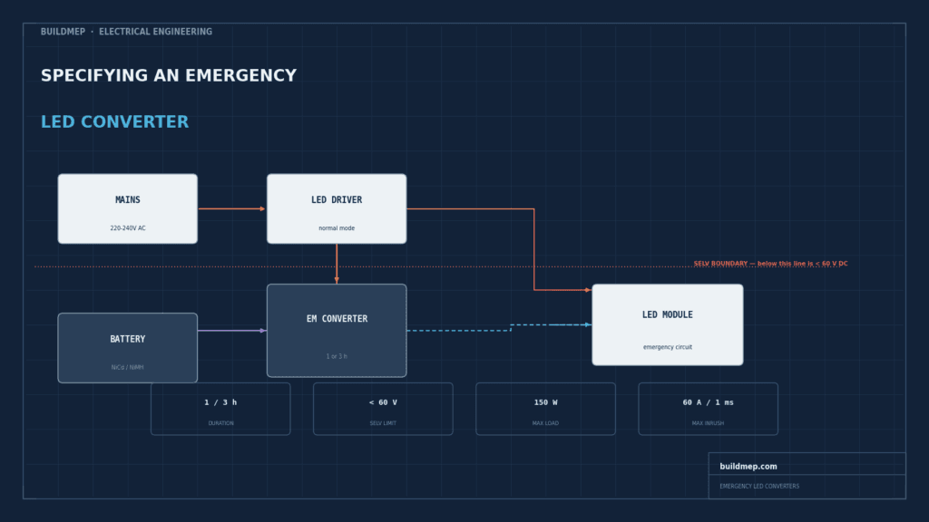
Specifying an emergency LED converter looks straightforward until you sit down with the actual datasheet. There’s a duration to set, a power rating to match, a forward voltage range to check, a maximum current the connected driver is allowed to draw, a battery chemistry to pick, and a wiring arrangement to decide on. Get one of those wrong and the failure isn’t always obvious at handover. Sometimes it’s a false battery fault. Sometimes it’s an escape route light that doesn’t hold code duration when it actually matters.
This guide works through the real selection criteria using Tridonic’s EM converterLED BASIC 50V range as the worked example, since its datasheet clearly exposes each decision. The selection logic applies whichever brand you specify. Start by separating the normal driver function from the emergency function, then work through duration, output power, voltage, driver compatibility, battery and commissioning.
LED Driver vs Emergency Converter: The Essential Difference
An LED driver is the normal power supply for the LED module. It converts the mains input into regulated output matched to the module’s voltage and current. An emergency converter is a separate changeover, charging and battery system that keeps the selected LED module operating after the normal mains supply fails. A standard luminaire therefore needs a driver for normal operation; it needs an emergency converter only when the fire strategy or local code requires emergency lighting.
| Check | LED driver | Emergency converter |
|---|---|---|
| Primary role | Powers the LED during normal operation | Supplies backup power during mains failure |
| Energy source | Mains input converted to regulated LED output | Charged battery pack and changeover circuit |
| Normal state | Continuously active while the luminaire is on | Charging and monitoring, unless used in a maintained arrangement |
| Main selection checks | Output current, voltage range, wattage, dimming protocol and SELV classification | Duration, emergency output, battery, switchover, test method and driver compatibility |
| Typical standards | Driver and controlgear product standards | Emergency luminaire, escape-lighting and local fire-code requirements |
Maintained and Non-Maintained Operation
In a maintained arrangement, the emergency luminaire is illuminated during normal conditions and remains illuminated from its battery during a power failure. In a non-maintained arrangement, the emergency light is normally off and switches on only when the normal supply fails or during a test. The correct arrangement comes from the fire strategy and the intended use of the space, not from the converter alone.
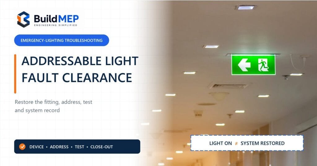
Typical applications include escape routes, final exits, stairwells, changes of direction, fire-fighting equipment locations and open-area anti-panic lighting. Confirm the required illuminance, duration, testing method and monitoring arrangement against the applicable local rules before ordering equipment.
What This Kind of Converter Actually Does
A converter like this sits between the mains supply, the normal LED driver, and a small battery pack. Its job is narrow but specific: the moment it detects mains failure, in under a quarter of a second on this model, it switches the connected LED module over to run from the battery. When mains returns, it switches back and starts recharging.
This is non-maintained operation. Unlike a maintained luminaire that stays lit continuously from a battery-backed circuit, a non-maintained converter only actually lights the LED during a genuine outage or a manual test. A three-terminal switching arrangement is what makes the transition clean: two connections handle physically changing the LED module’s supply between driver and battery, while a third delays reconnecting the LED driver itself, so switchover doesn’t create a flicker or a current spike.
Step 1: Duration Is Set by Code, Not Preference
The rated duration isn’t a design choice you get to make freely. EN 1838 sets a minimum of one hour for standard escape route and anti-panic lighting, extending to three hours in higher-risk situations such as sleeping accommodation, and some national annexes or local fire authorities set three hours as the baseline for entire building categories regardless of risk. Check your local code and the building’s fire strategy before assuming one hour is acceptable.
On this converter range, duration is set by a physical link, essentially a jumper, and here’s the detail that catches people out: it’s read only the first time the unit powers up. Change the link after the unit has already been commissioned, and unless both the mains and the battery are fully disconnected for a full 10 seconds before reconnecting, the converter will report a false battery fault. If a duration decision changes on site after first power-up, build that disconnect step into the commissioning sequence, not just the physical link swap.
Step 2: Power Is a Separate Decision From Duration
Confusingly, changing the duration link on this range doesn’t change how much power the converter delivers in emergency mode. The three models in the family, differentiated by cell count, each deliver a fixed emergency output regardless of whether they’re set to 1 or 3 hours:
| Model | Cells | Emergency output power |
|---|---|---|
| BASIC 202 | 2 | 1.5 W |
| BASIC 203 | 3 | 2.4 W |
| BASIC 204 | 4 | 3.5 W |
So wattage and duration are answering two different questions. Wattage tells you how much LED module you can actually run in emergency mode. Duration tells you for how long. Undersize the wattage and the LED module runs dim, or only partially populated, during an outage even though the timing is correct.
Step 3: Voltage and SELV, Where Wiring Topology Changes the Answer
The forward voltage range on this converter covers 10 to 54 V DC, with the output classified SELV throughout, meaning under 60 V DC. That classification is what lets the LED-side wiring, the battery, the indicator LED and the test switch all be treated as safety extra-low voltage, simplifying separation requirements from the mains side.
Here’s the part that catches people out. Wire multiple LED modules in series off one converter and their forward voltages add together, and it doesn’t take many modules before the total climbs past that 60 V threshold. Wire the same modules in parallel instead, and the voltages don’t add, since each module still only sees its own forward voltage. Per Tridonic’s own installation and wiring instructions for this range, that’s precisely why parallel wiring is the way to add more LED modules to one converter while staying inside SELV. If a design needs several modules on one emergency circuit, series versus parallel is worth deciding deliberately rather than defaulting to whatever wires up easiest.
Step 4: Checking Compatibility With a Driver You Already Have
If emergency backup is being retrofitted onto an existing LED driver rather than specified from scratch, that driver has to sit inside limits the converter’s internal switching relay can actually handle. For this range, those limits are:
- Maximum output current: 2 A continuous, 2.4 A peak
- Maximum inrush current: 60 A for 1 ms, or 84 A for 255 μs
- Maximum output voltage applied to the converter: 450 V
- Maximum LED load: 150 W, and the load must be an LED module
Exceed any of those and the risk isn’t just poor performance, it’s stressing a relay rated for a specific switching duty. Check the driver’s own datasheet against these figures before wiring it in. Tridonic’s own guidance is to confirm compatibility with a short function test of several seconds rather than assuming the numbers work out on paper.
There’s also a lead length budget that’s easy to miss entirely. The maximum permitted lead length on the LED driver’s own output is a fixed figure in that driver’s datasheet, and the converter’s wiring run to the LED module counts against that same budget. So if a driver allows 3 metres of lead and the converter is wired with a metre of cable to the module, there’s effectively 2 metres left for the driver-to-converter run, not 3.
Enter the figures from your LED driver’s own datasheet. Each is checked against the EM converterLED BASIC’s maximum ratings.
Inrush is rated for a specific duration, not just a current, so enter both figures from the driver’s datasheet.
Limits shown are for the Tridonic EM converterLED BASIC range specifically. Confirm the same four figures against your own converter’s datasheet if you’re specifying a different model or brand, and always confirm with a short function test before full installation.
Step 5: Battery Chemistry and the Maintenance Timeline Nobody Plans For
NiCd and NiMH are both used across this range, and which chemistry gets paired with which model depends on the duration setting as much as the model itself. Looking at Tridonic's own battery selection table for this converter, the same 2-cell converter pairs with a NiMH pack for 1-hour duration and a higher-capacity NiCd pack for 3-hour duration. Duration doesn't just change a setting on the converter. It changes which battery is supposed to be fitted.
Worth planning around at handover: the converter itself carries a 5-year guarantee and a rated lifetime up to 100,000 hours, but the battery inside has a 4-year design life and only a 2-year guarantee. Budget for at least one battery replacement within the converter's service life, and don't assume a fault reported after year 3 or 4 means the whole unit has failed.
Case temperature affects that lifetime figure more than people expect, too. On this range, a converter running at 65°C case temperature is rated for over 100,000 hours, but that drops to somewhere around 97,000 hours at 70°C and to roughly 69,000 hours at 75°C, depending on the exact model. If the converter is going into a tightly sealed luminaire with poor heat dissipation, the real-world service life can end up meaningfully shorter than the number on the box.
Step 6: Wiring Topology, How Many Modules and How
Three arrangements cover most installations:
- Standalone: one LED module, running in emergency mode only, no separate mains driver involved
- Combined: one LED module runs from a standard mains driver in normal operation and switches to the converter's battery in emergency mode
- Multiple modules: several LED modules wired in series or parallel off one converter, with only the connected module or modules actually running from the battery in emergency mode while the rest continue on the mains driver
Whichever arrangement gets used, decide series versus parallel only after checking the SELV voltage math in Step 3, not before.
Quick Selection Checklist
- Confirm required duration against your local emergency lighting code and fire strategy, not a default assumption
- Match emergency output power to the LED module's actual load, with some margin
- Check the LED module's forward voltage falls inside the converter's rated range
- If wiring multiple modules, calculate total forward voltage for series wiring and confirm it stays under the SELV threshold
- If retrofitting onto an existing driver, check that driver's current, inrush and voltage figures against the converter's maximum ratings
- Add the converter's own LED lead length to the driver's lead run and confirm the total stays inside the driver's maximum
- Confirm the correct battery chemistry and capacity for the duration selected, not just for the model number
- Check the duration link position before first power-up, since changing it afterward needs a full disconnect and reset
The BASIC 50V Range at a Glance
| Model | Article number | Cells | Emergency power | Duration options | Dimensions |
|---|---|---|---|---|---|
| BASIC 202 NiCd/NiMH 50V | 89800558 | 2 | 1.5 W | 1 or 3 h | 179 x 30 x 21 mm |
| BASIC 203 NiCd/NiMH 50V | 89800559 | 3 | 2.4 W | 1 or 3 h | 179 x 30 x 21 mm |
| BASIC 204 NiCd/NiMH 50V | 89800560 | 4 | 3.5 W | 1 or 3 h | 179 x 30 x 21 mm |
Specifications verified against the manufacturer's official product listing and datasheet (08/26-EM070-27).
Common Mistakes Worth Avoiding
- Changing the duration link after commissioning without disconnecting mains and battery for the full 10 seconds, triggering a false battery fault
- Wiring several LED modules in series without checking whether the combined forward voltage pushes past the SELV threshold
- Pairing an existing LED driver with a converter without checking its inrush and peak current against the converter's relay rating
- Forgetting the converter's own lead run counts against the driver's maximum permitted lead length
- Assuming the battery and converter share the same service life, and being surprised by a battery fault years before the converter itself is due for replacement
- Installing the converter in a poorly ventilated luminaire cavity and getting a shorter real-world lifetime than the datasheet headline figure
Frequently Asked Questions
How do I choose the duration for an emergency LED converter?
Duration is set by your local emergency lighting code and the building's fire strategy, not by preference. EN 1838 sets a one-hour minimum for standard escape routes, rising to three hours for higher-risk occupancies such as sleeping accommodation, and some jurisdictions require three hours as a baseline regardless. Check the applicable code before specifying.
Does changing the duration setting change the converter's power output?
Not necessarily. On the Tridonic BASIC range, emergency output power is fixed per model regardless of whether duration is set to 1 or 3 hours. Power and duration are matched to the load and the code requirement separately.
Why does wiring LED modules in series affect SELV compliance?
Forward voltages add together in a series circuit, so several modules in series can push the total voltage past the 60 V SELV threshold even if each module is well within range individually. Wiring the same modules in parallel avoids this, since each module's forward voltage stays independent.
What happens if my existing LED driver exceeds the converter's rated limits?
The converter's internal switching relay is rated for specific maximum current, inrush and voltage figures. Exceeding them risks damaging the relay over time, even if the system appears to work initially. Always check the driver's datasheet against the converter's compatibility limits before wiring it in.
How long do the batteries in an emergency LED converter actually last?
Typically shorter than the converter itself. A converter may carry a lifetime rating up to 100,000 hours and a 5-year guarantee, while its battery has a 4-year design life and a 2-year guarantee. Plan for at least one battery replacement within the converter's service life.