Practical BMS Controls Guide
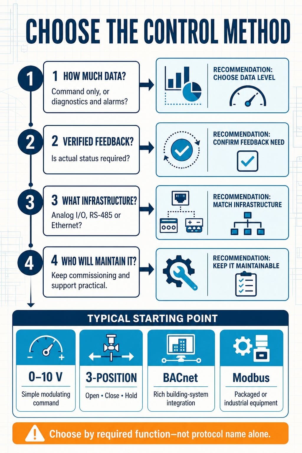
The actuator submittal offers BACnet, Modbus, 0–10 V and 3-position control. They all move the same valve or damper—so which one should you specify? The answer is not simply “digital is better.” It depends on what the BMS needs to command, monitor, commission and maintain.
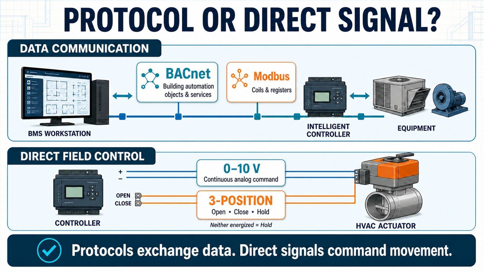
BACnet and Modbus exchange data between intelligent devices. A 0–10 V signal sends a direct analog command to one device. Three-position control uses separate open and close commands, normally with the actuator holding when neither is active. Choose the simplest method that delivers the required control, feedback, diagnostics, interoperability and lifecycle support.
The comparison in one table
| Method | What travels | Typical wiring/network | Best fit | Main limitation |
|---|---|---|---|---|
| BACnet | Named building-automation objects, properties and services | BACnet/IP over Ethernet or BACnet MS/TP over an RS-485 physical layer | Integrated building systems needing standardized data and richer diagnostics | Engineering quality still depends on profiles, point lists, addressing and commissioning |
| Modbus | Coils and registers read or written using defined function codes | Modbus TCP over Ethernet or Modbus RTU over an RS-485 physical layer | Plant equipment, meters, VFDs and packaged systems with a known register map | Register meaning and scaling are largely product-specific |
| 0–10 V | One continuous voltage representing a command or value | Point-to-point analog wiring plus a common/reference | Simple modulating valves, dampers and VFD speed commands | Limited information; feedback requires a separate signal |
| 3-position | Open/extend or close/retract command; no command means hold | Two switched controller outputs plus power/common as required | Simple floating control where precise network data is unnecessary | Position is usually inferred from travel time unless separate feedback is provided |
What BACnet gives you
BACnet was developed specifically for building automation. Instead of exposing only anonymous numbers, a BACnet device represents information through standardized objects and properties—for example an analog value, binary output, schedule or alarm-related information. That common model is why BACnet is usually the more natural choice for integrating HVAC controllers and multiple building systems.
But “BACnet compatible” is not a complete integration specification. The project still needs the transport, device profile or capabilities, required points, writable commands, units, alarm behavior, trend requirements, network addressing and responsibility for testing. BTL certification is useful evidence of conformance, but it does not replace a project point list and sequence of operation.
What Modbus gives you
Modbus is widely used because it is straightforward and well supported in industrial and packaged equipment. A client requests data from, or writes data to, a server using function codes. The data model includes coils, discrete inputs, input registers and holding registers.
The protocol standardizes how those values are exchanged, but the equipment manufacturer’s register map tells you what register 40021 actually means, whether it is writable, its data type, byte order, units and scaling. That documentation is part of the integration—not an optional extra.
How 0–10 V control works
A controller varies a voltage and the actuator interprets that voltage as a requested position. In a simple linear arrangement, 0 V may represent 0% and 10 V may represent 100%. Some products instead use 2–10 V, reverse acting, split ranges or configurable minimum and maximum values. Read the actuator data sheet rather than assuming.
Analog control remains an excellent choice when the BMS only needs to command one modulating device and perhaps read one separate feedback signal. It is easy to understand with a meter and does not require protocol mapping. The trade-off is that a voltage command cannot by itself report alarms, operating hours, actual torque, internal temperature or detailed device status.
0–10 V signal scaler
Convert between a voltage and the corresponding engineering value. Change the ranges to match the actual product data sheet.
This is a linear conversion tool. It does not prove that the connected actuator uses a linear characteristic or accepts the entered signal range.
How 3-position control works
A 3-position actuator normally receives one command to move in one direction and another to move in the opposite direction. With neither output active, it holds its current position. Siemens describes this directly for its applicable actuators: voltage at one input extends the stem, voltage at the other retracts it, and no voltage maintains the current position.
The controller often estimates position from the time it has driven the actuator. If a 120-second actuator is commanded open for 30 seconds, the estimated movement is about 25% of full travel. This is useful, but it is not the same as measuring actual position. Power interruptions, manual operation, binding and travel-time variation can create drift, which is why controllers may periodically drive to an end stop to resynchronize.
3-position travel-time estimator
Which one should you choose?
| If the application needs… | Usually start by considering… | Then verify… |
|---|---|---|
| One simple modulating command | 0–10 V or 2–10 V | Signal range, impedance/loading, common reference, action and separate feedback |
| Simple open/close movement with hold | 3-position/floating | Output voltage/type, interlocking, running time, synchronization and feedback needs |
| Rich HVAC integration across vendors | BACnet | Transport, BTL listing, profiles/capabilities, point list and network architecture |
| Packaged equipment or industrial plant data | Modbus | RTU versus TCP, register map, addressing, data types, scaling and byte order |
| Safety-critical action | Approved hardwired or listed control arrangement as required | Applicable codes, sequence, listing, fail-safe behavior and authority requirements |
Worked examples
Example 1: chilled-water control valve
The BMS needs only a modulating command and position feedback. A 0–10 V command plus a separate 2–10 V feedback may be simpler to commission and replace than a networked actuator. If the owner also needs actuator alarms, operating data and remote configuration, a network option becomes more valuable.
Example 2: VFD serving an AHU
A hardwired speed command may run the fan, but the BMS may also need current, frequency, energy, run hours, fault code and reset capability. BACnet or Modbus can carry those additional points—provided the point list, control priority and fallback behavior are engineered clearly.
Example 3: packaged chiller
The chiller may offer both BACnet and Modbus. Choose based on the project standard, available gateway-free integration, the quality of the exposed point set and the facility team’s support capability—not simply the protocol name on the option list.
Commissioning checklist
| Check | What to confirm |
|---|---|
| Physical layer | Cable, topology, polarity, shielding/grounding approach, termination and permitted segment limits |
| Addressing | Unique device/node addresses, IP settings where applicable, baud rate and parity |
| Point definition | Name, unit, read/write status, range, scaling, normal state and alarm meaning |
| Command priority | Who can command the point, how local/manual commands behave and how overrides are released |
| Failure response | Behavior after signal loss, network loss, controller restart and power restoration |
| End-to-end test | Command from the BMS, observe the physical device, confirm feedback and simulate a relevant fault |
| Handover | Final addresses, point list, register map, backups, passwords/access policy and as-built drawings |
Frequently asked questions
Is BACnet better than Modbus?
Not universally. BACnet has a building-automation-specific object and service model. Modbus is simple and common in industrial and packaged equipment. The better choice is the one that exposes the required data reliably and fits the project architecture and support capability.
Does RS-485 mean Modbus?
No. RS-485 describes an electrical physical layer. Both Modbus RTU and BACnet MS/TP commonly use RS-485, but they are different protocols and cannot communicate merely because the wiring is similar.
Can 0–10 V provide feedback?
A separate analog output from the actuator can provide position feedback if the model supports it. The command wire itself normally represents the requested value, not proof of actual position.
Is 3-position the same as on/off control?
No. On/off typically drives between two end positions. Three-position control can stop between them by timing open and close commands, although actual intermediate position may be inferred rather than measured.
Can a gateway solve any protocol mismatch?
A gateway can translate supported data, but it cannot create points the source device does not expose or fix an incomplete sequence. It also becomes another component to configure, document and maintain.
Technical references
- BACnet International — About BACnet
- BACnet International — BACnet Glossary and current standard references
- Modbus Organization — Specifications and implementation guides
- Modbus Application Protocol Specification V1.1b3
- Siemens — 3-position and 0–10 V actuator technical operation
Engineering note: Always confirm the final wiring, network design, control action and failure behavior against the selected equipment documentation, project sequence and applicable codes.