BuildMEP practical fire-alarm installation guide
This fire alarm conduit installation method statement turns an approved containment route into a slab, wall or surface installation that can be inspected, proved clear and handed over before cable pulling begins.
Decision brief
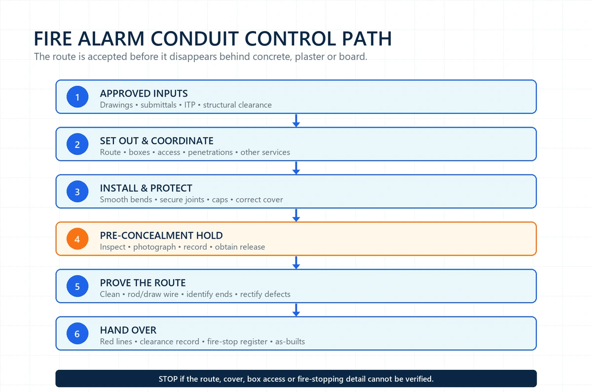
Do not conceal a fire-alarm conduit route until four things are true: its route and materials match the approved documents; boxes and joints are secure and accessible; the bore is protected or proved clear at the required stage; and the applicable inspection hold point has been released.
The exact conduit material, size, classification, support spacing, bend arrangement, segregation and fire-stopping system remain project decisions. They depend on the adopted code, fire strategy, cable system, environment, approved submittal, manufacturer instructions and authority requirements.
Download the editable site template
Use the PDF as a starting point, then replace every project field and obtain the required approvals before work starts.
What the method statement must control
The document is useful only if it controls the transition from drawing to concealed work. It should name the information needed before setting out, assign responsibility for changes and inspections, define installation and protection steps, state acceptance criteria, and identify the records that prove the route remains usable.
Use this guide for
- rigid conduit in reinforced-concrete slabs;
- concealed conduit and sunk boxes in suitable walls;
- surface conduit shown on approved drawings;
- pre-pour, pre-plaster and pre-cable-pull checks; and
- clearance, red-line and handover records.
Do not use it to authorize
- unapproved routing or device relocations;
- reinforcement cutting or post-tension slab drilling;
- chasing a structural, precast or specialist wall without clearance;
- an untested fire-stop product combination; or
- complete fire-alarm commissioning.
Applicable standards and project documents
For a UK-oriented non-domestic project, the following documents may form part of the reference framework. They do not override the contract, adopted legislation or authority decision:
- BS 5839-1:2025 — the current code of practice for design, installation, commissioning and maintenance of fire detection and fire-alarm systems in non-domestic premises; it superseded the 2017 edition.
- BS EN 61386-1:2008+A1:2019 — current general requirements for metallic, non-metallic and composite conduit systems and fittings.
- BS EN IEC 61386-21:2021+A11:2021 — current particular requirements for rigid conduit systems.
- BS 7671:2018+A4:2026 — the newly published IET Wiring Regulations edition where applicable. The IET states that BS 7671:2018+A3:2024 remains valid during the transition only until 15 October 2026; confirm the edition adopted by the project.
Also list the exact project specification clauses, approved material submittals, fire-alarm layouts and schematics, architectural and structural drawings, coordinated MEP drawings, builders-work details, fire strategy, fire-stopping details, manufacturer instructions, risk assessment, inspection and test plan (ITP), and local fire or civil-defence authority requirements.
Edition check: 2 September 2026. Recheck publisher status and the project’s adopted editions before reusing this page in a later submission.
Responsibilities and change authority
| Role | Controlled responsibility |
|---|---|
| Project manager | Resources, programme, interfaces and implementation of approved documents. |
| Project engineer | Method statement, material approvals, coordination, technical queries and work planning. |
| Site engineer | Setting out, daily coordination, installation control and red-line updates. |
| QA/QC engineer | Material and work inspections, ITP records, test records and nonconformance close-out. |
| Fire-alarm specialist | System-route, cable, interface, accessibility and manufacturer requirement checks. |
| HSE officer | Risk controls, permits, access equipment, dust control, briefings and emergency arrangements. |
| Supervisor and installers | Workmanship, approved tools, protection, housekeeping and immediate defect reporting. |
The approved method must identify who can authorize a route or box-position change. Site personnel should not improvise a new loop path, omit an accessible draw-in point or move a device box without a recorded technical approval.
Pre-installation release
Before work starts, confirm the following:
- Approve the coordinated fire-alarm and MEP drawings.
- Approve the conduit, fittings, boxes and fire-stop submittals.
- Confirm conduit sizes and the cable-fill basis.
- Confirm box coordinates, mounting levels and future access.
- Coordinate routes with ducts, pipes, openings and reinforcement.
- Identify post-tension zones and structural restrictions.
- Approve required sleeves and rated-penetration details.
- Release formwork, wall substrate and work access.
- Issue permits and brief the task risk assessment.
- Verify competent installers and inspected tools.
At material receipt, compare type, size, classification, manufacturer and condition with the approved submittal. Reject cracked, distorted, corroded or incompatible components. Store straight conduit on supports, keep fittings labelled and covered, and protect non-metallic products from heat, ultraviolet exposure and chemicals in accordance with their manufacturer’s instructions.
Method for fire alarm conduit in concrete slabs
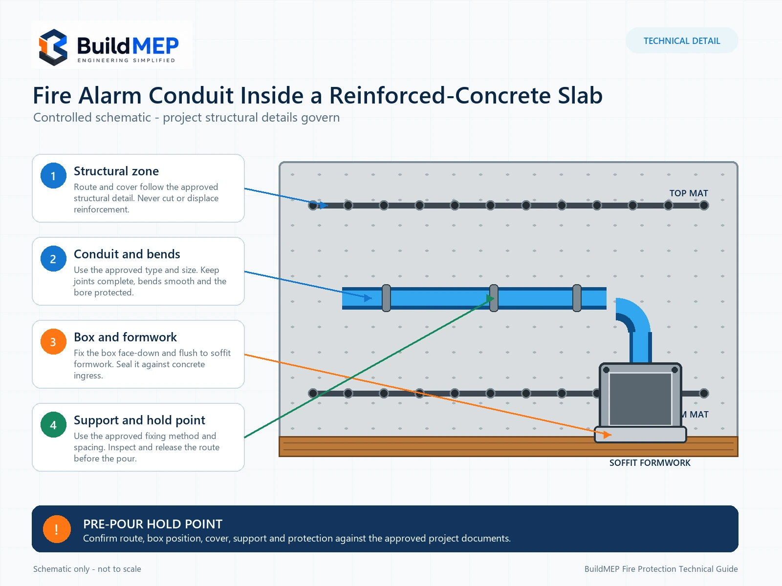
Obtain an area release
Confirm formwork, reinforcement and access status with the responsible civil or structural team. Review the pour sequence and the deadline for the pre-pour inspection.
Set out from controlled references
Transfer routes and box positions from the latest approved drawing using grids or fixed structural references. Confirm slab drops, wall rises and panel or interface destinations before fixing.
Fix boxes against movement and concrete ingress
Secure each device, junction, inspection or draw-in box so it cannot float, rotate or shift during concrete placement and vibration. Seal unused entries and keep the box face at the required finished level.
Prepare conduit and fittings
Cut square, ream or deburr the bore, use compatible fittings and form smooth bends with the approved tool. Reject flattened, split or kinked sections.
Install without compromising the structure
Complete joints and secure the route by the approved fixing method. Maintain the required cover and keep clear of congested reinforcement, post-tension tendons, pour strips and locations where containment could obstruct compaction or create a weak plane. Never cut reinforcement or reduce structural cover without written approval.
Provide usable, accessible draw-in points
Base their location on route length, bend accumulation, cable-pulling assessment, conduit size and project rules. Keep every cover intended for future access reachable after ceilings, finishes and joinery are installed. “One box every 8 m” is not a universal rule.
Protect all openings
Cap conduit ends and seal boxes against slurry. Secure draw wires or cords so they cannot become buried, lost or pulled into the route.
Inspect and release before the pour
Check route, size, joints, bend quality, boxes, support, cover, protection and coordination. Photograph the concealed work with an identifiable area or grid reference and obtain the ITP release.
Monitor the concrete placement
Assign a competent person to observe vulnerable containment from a safe position. Correct visible displacement, damaged protection or opened joints only when site controls allow it; do not enter an unsafe active-pour area.
Clean and prove slab routes after concrete
After formwork removal and a safe-access release, locate the boxes, remove temporary protection carefully, clean residue and check faces, entries and covers for damage or displacement. Pass the approved draw wire, rod, mandrel or other specified proving device through the complete route. Confirm that the bore is free from concrete, debris, water and sharp obstructions and that both ends match the recorded destination.
Replace damaged or missing draw cords, label route direction where useful, record defects, and repair only through an approved method. Update the clearance record and red-line drawing while the evidence is still available.
Method for concealed conduit in walls
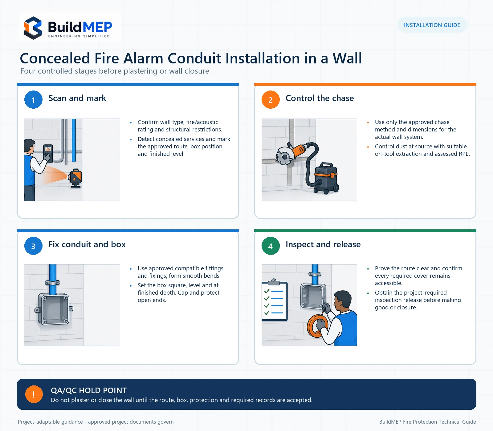
Confirm the wall can be chased
Identify the wall construction, reinforcement, concealed services, fire rating, acoustic requirement and finish. Obtain structural or civil clearance where required; chasing may be prohibited in structural, precast or specialist systems.
Set out routes and boxes
Use approved dimensions and levels, then compare them with doors, ceilings, finishes, joinery and equipment before cutting.
Scan, isolate and control access
Check for concealed electrical and water services and apply the project permit and isolation procedure. Barricade the work area and provide suitable lighting and housekeeping.
Control silica dust at source
Reduce or avoid chasing where practicable. For UK work, HSE guidance identifies concrete chasing as high risk and calls for suitable on-tool extraction plus task-appropriate respiratory protective equipment (RPE). Select, fit-test, inspect and maintain controls through the project’s COSHH assessment; do not treat an ordinary vacuum or a disposable mask of unspecified performance as an adequate system.
Form only the approved chase
Use the approved cutting method and dimensions. Avoid uncontrolled breaking, excessive horizontal chases, reinforcement damage and cutting into lintels or columns.
Fix and protect the installation
Set boxes square, level and at the correct finished depth. Make smooth bends and secure joints; fix the conduit so it cannot move during making good. Cap every open end and protect box interiors.
Inspect before closure
Prove the route clear and obtain the required inspection before plastering, boarding or wall closure. Release making good only after defects are closed and the selected repair method preserves the wall’s fire, acoustic and finish performance.
Surface routes, bends and penetrations
For exposed conduit, set out straight coordinated routes, use project-approved support spacing, and provide additional support near boxes, changes of direction and terminations where required. Select materials and finishes for corrosion, ultraviolet exposure, moisture, impact and vibration; provide approved movement arrangements at structural or thermal movement joints.
Plan every route for the specified cable, not just for an empty conduit. Confirm diameter, fill, minimum bend radius, permitted bends between accessible draw-in points, pulling force limits, segregation and electromagnetic-compatibility requirements. Avoid hidden couplings and inaccessible covers. Do not use a conduit fitting as a substitute for a tested fire-stop system.
Rated walls and floors
Identify the barrier construction and fire-resistance requirement before forming the opening. Use a tested and approved fire-stopping detail that covers the substrate, conduit material, conduit size, service configuration, annular space and backing materials actually installed. Record product and batch information where required, photograph the installation, apply its identification label and add it to the project fire-stop register.
Inspection and testing: keep the stages separate
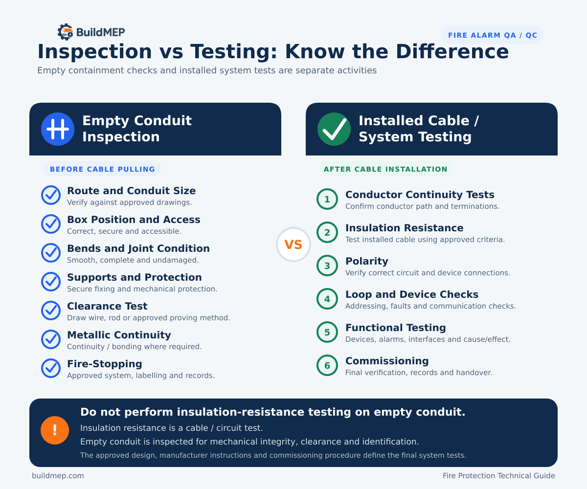
| Stage | Checks | Typical evidence |
|---|---|---|
| Empty conduit | Route, type, size, joints, bends, support, boxes, accessibility, caps, cleanliness, clear bore, identification, penetration seals, and metallic continuity or bonding where required. | Work inspection request, photographs, clearance record, continuity record and fire-stop register. |
| After cable installation | Conductor continuity, insulation resistance, polarity, earth-fault monitoring, loop or device checks and manufacturer-required cable tests. | Approved cable and circuit test sheets with instrument and calibration details. |
| Complete system | Addressing, cause and effect, interfaces, alarm devices, fault monitoring, audibility or visual coverage, documentation and final acceptance. | Commissioning procedure, cause-and-effect records, certificates and authority or consultant sign-off. |
Each test should have a named method, acceptance criterion, instrument where relevant, responsible person and record. Avoid a single line that says only “test conduits and cables.”
Sample inspection and test plan
| Stage | Inspection or test | Suggested status | Record |
|---|---|---|---|
| Material delivery | Approval, type, size, classification and condition | Review / witness | Material inspection request |
| Pre-start | Drawings, permits, clearances and setting out | Review | Pre-start checklist |
| Slab installation | Route, boxes, joints, supports, cover and protection | Hold before pour | Work inspection request |
| Wall installation | Chase, route, boxes, fixing and protection | Hold before closure | Work inspection request |
| Post-concrete | Box condition, identification and clear bore | Witness | Conduit clearance record |
| Metallic containment | Continuity and bonding where applicable | Witness | Test sheet |
| Rated penetrations | Approved system, installation and labelling | Hold / witness | Fire-stop inspection and register |
| Before cable pull | Draw wire, clear route and accessible covers | Review | Cable-pull release |
| Handover | Red lines, as-builts, test records and NCR closure | Review | Handover dossier |
Worked site handoff: Level 3 slab, Zone C
Assumed project condition: a rigid conduit branch serves three ceiling devices from an accessible corridor draw-in box. The approved drawing shows a slab route crossing a duct zone and terminating at three device drops. The project ITP requires a pre-pour hold point and a post-strip clearance record.
- The site engineer checks the controlled drawing revision, the conduit submittal, the structural no-go zones and the ceiling-device coordinates.
- The team sets out the draw-in box and drops from grid references, then shifts the route around the coordinated duct opening only after the engineer records the approved change.
- Installers fix the box and conduit, maintain the structural cover shown by the approved detail, cap every end and secure the draw cord.
- QA/QC records the grid and zone in the photographs, checks the full route and obtains the pre-pour release.
- After stripping, the team cleans the boxes and proves each complete route to its destination. One branch does not pass the specified proving device, so it is logged as a defect; the cable-pull release for that branch remains closed.
- The branch is repaired using the approved method, proved again, identified, and added to the clearance record. The red-line drawing, photographs and accepted record enter the handover dossier.
Decision completed: only the two routes that passed were initially available for cable pulling. The blocked branch did not become a cable-installation problem because the hold/release system exposed it before the next trade relied on it.
Common failure modes and corrections
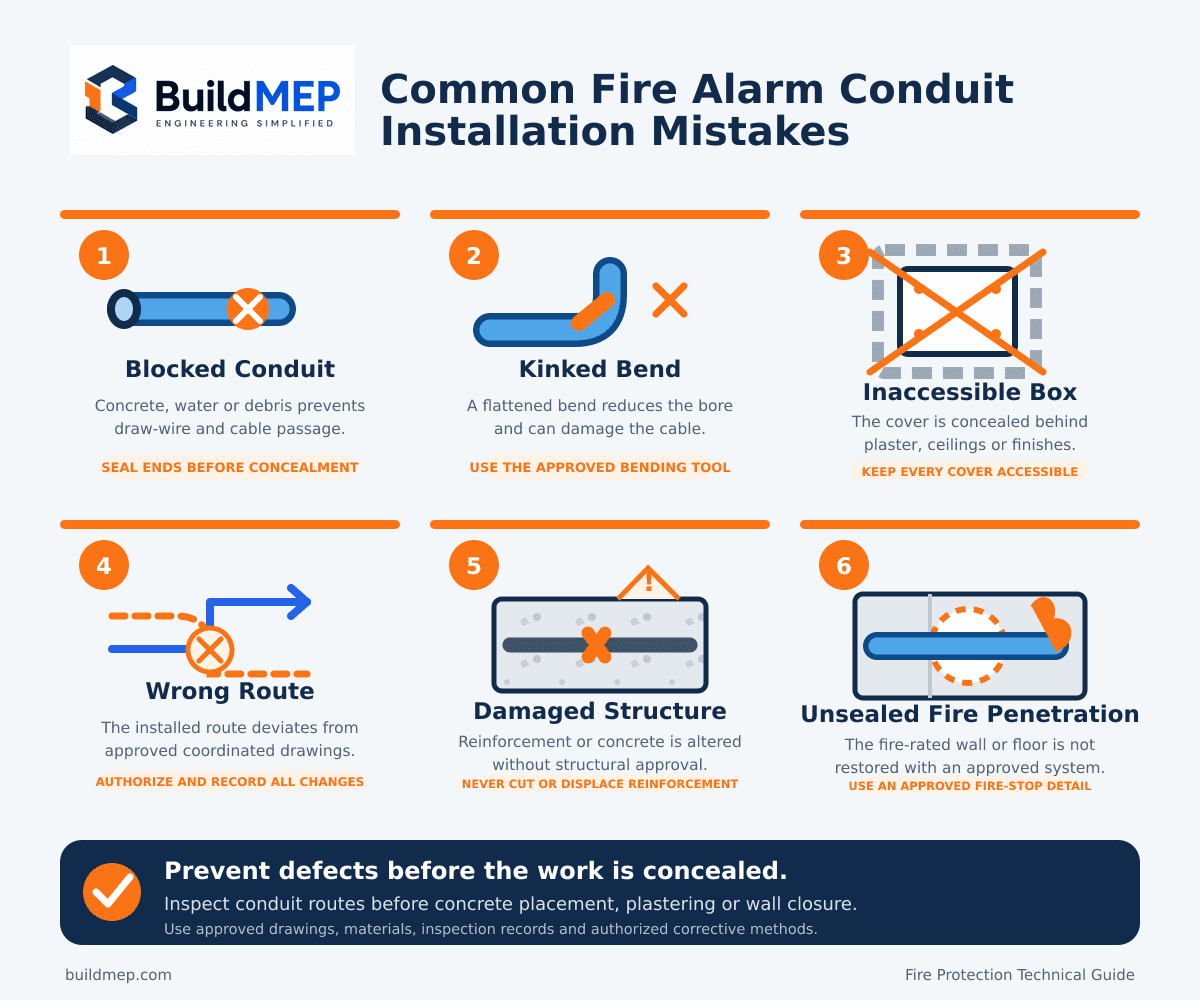
| Mistake or cause | Consequence | Field symptom | Correction |
|---|---|---|---|
| Outdated drawing | Wrong termination or loop route | Box aligns with an obsolete ceiling/device position | Stop, verify revision, raise a technical query and update red lines. |
| Open conduit or box | Concrete or plaster blockage | Draw rod stops; concrete residue fills the box | Cap and seal before concealment; repair through an approved method and prove again. |
| Kinked or excessive bends | Cable damage or excessive pulling force | Mandrel or draw wire binds at the bend | Reform or replace the route; add only approved accessible draw-in points. |
| Hidden box cover | No future pulling or maintenance access | Cover disappears behind a ceiling, finish or joinery | Coordinate access before closure and relocate only with approval. |
| Unapproved structural work | Loss of cover or structural damage | Cut reinforcement, drilled tendon zone or oversized chase | Stop work, isolate the area and obtain structural assessment and disposition. |
| Generic penetration seal | Fire barrier performance cannot be demonstrated | Mortar or sealant has no system reference or label | Use the approved tested system and complete the fire-stop record. |
| Poor red-line control | Concealed route cannot be traced | Installed route differs from as-built drawing | Mark changes and photographs while work remains visible. |
Health, safety and environmental controls
Use a task-specific risk assessment and permits for the actual site and jurisdiction. Typical hazards include open slab edges and floor openings, falling objects, active concrete placement, wall-chasing dust, noise, vibration, sharp edges, portable tools, concealed or live services, manual handling, poor access and lighting, and hot work where the selected method creates sparks or heat.
For work at height, apply the hierarchy: avoid the exposure where reasonably practicable, prevent falls using a safe place or suitable collective protection, and only then select personal measures or fall-arrest controls supported by suitable anchors and rescue planning. A generic instruction that a harness becomes mandatory above an arbitrary height is not a substitute for the legal framework, access method and risk assessment.
- Brief the approved risk assessment and toolbox talk.
- Inspect access equipment, guards, leads and extraction.
- Control slab edges, openings and exclusion zones.
- Use dust extraction and suitable, fit-tested RPE where required.
- Provide assessed eye, hearing, hand, foot and head protection.
- Plan handling of long conduit lengths.
- Maintain clean access and remove waste promptly.
- Provide emergency and rescue arrangements for the task.
Acceptance and handover checklist
- Confirm approved materials and compatible fittings.
- Compare routes, sizes and positions with approved drawings.
- Verify secure, undamaged conduit, boxes and supports.
- Confirm smooth bends and a usable bore.
- Prove routes clean and clear by the approved method.
- Verify access to every required cover.
- Confirm metallic continuity and bonding where required.
- Verify structural cover and approved clearances.
- Confirm rated penetrations are sealed and registered.
- Close nonconformances before release.
- Record red lines, photographs and accepted inspections.
- Issue as-builts, test records and the handover dossier.
Frequently asked questions
Can PVC conduit be used for fire alarm cables?
Only when the adopted regulations, approved fire-alarm design, fire strategy, specification, authority requirements and product classification permit it. Normal electrical practice or lower cost alone is not an approval basis.
How many bends are allowed between draw-in boxes?
Use the approved project rule and conduit-system instructions, then check actual route geometry and the selected cable-pulling limits. Do not publish a universal number without the governing source and conditions.
When is slab conduit inspected?
Inspect and release it after installation and coordination but before concrete placement. Inspect again after formwork removal and cleaning, then prove the route before cable pulling.
Does an empty conduit need insulation-resistance testing?
No. Insulation resistance applies to installed cables or circuits. Empty conduit needs mechanical, clearance and identification checks; metallic containment may also require continuity or bonding verification.
Does this method statement commission the fire alarm system?
No. Commissioning requires separate approved procedures for installed cables, devices, programming, cause and effect, alarm outputs, interfaces, monitoring, documentation and acceptance.
Evidence trail
- BSI, BS 5839-1:2025 — publisher status, scope, publication date and supersession of the 2017 edition.
- BSI, BS EN 61386-1:2008+A1:2019 — current general conduit-system scope and status.
- BSI, BS EN IEC 61386-21:2021+A11:2021 — current rigid-conduit-system edition.
- IET, BS 7671 edition checker — Amendment 4:2026 publication and the Amendment 3:2024 transition ending 15 October 2026.
- UK HSE, Chasing concrete and raking mortar — high-risk silica exposure, on-tool extraction and RPE control guidance.
- UK HSE, Introduction to working at height safely — avoidance, prevention, mitigation and collective-before-personal protection hierarchy.
The BSI pages confirm edition and high-level scope; access to the complete standards and the project’s adopted documents is still required for clause-level design and installation decisions.