


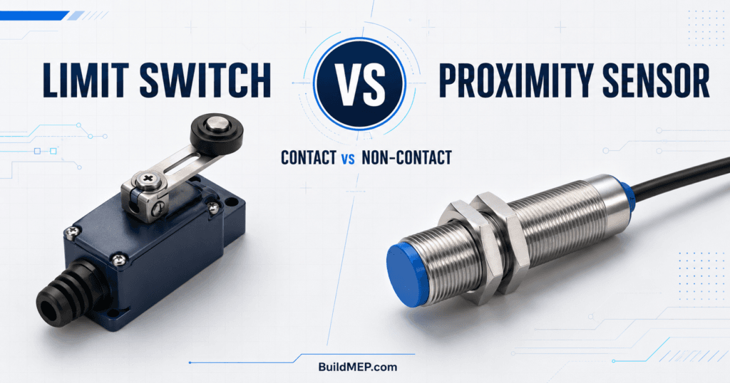
Limit Switch vs Proximity Sensor is a confusing topic for the engineering professionals. The control system can be made to know that an object has arrived at a position by either using limit switches or proximity sensors. What is significant is the way they detect it.
The moving object has to physically move the mechanical limit switch to change the state of the switch. A proximity sensor is a sensor that can sense a target without touching it. This distinction has an impact on service life, switching speed, repeatability, wiring, maintenance, environmental suitability and cost.
Both technologies are not necessarily superior in all scenarios. For any slow moving gate or valve mechanism, a good quality roller-lever limit switch might be the most feasible solution for reaching the end position. The non-contact inductive sensor is typically better for a high cycle metal-part detection on conveyor. The proper choice is determined by the target, movement, environment, control input and desired safety function.
This guide offers an explanation from an engineering point of view and provides practical examples of industrial automation, HVAC controls, BMS panels, conveyors, and packaging equipment and machinery.
In simpler terms, use a limit switch if all that is required is a contact for direct contact, the rate of movement is relatively slow, a simple dry contact is desired, and cost is a factor. Select a proximity sensor if you require non-contact sensing, high switching frequency, enhanced repeatability, and/or minimized mechanical wear. Please check the details of the datasheet and application for details.

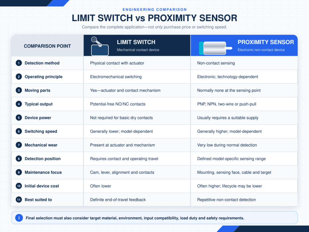
Quick comparison
| Feature | Mechanical limit switch | Proximity sensor |
|---|---|---|
| Detection method | Physical contact with an actuator | Non-contact detection |
| Typical operating principle | Electromechanical contacts | Electronic sensing principle |
| Moving parts | Yes | Normally no |
| Typical output | Potential-free NO/NC contacts | PNP, NPN, two-wire, push-pull or other electronic output |
| External power | Not usually required for basic dry contacts | Usually required |
| Switching speed | Generally lower | Generally higher |
| Repeatability | Good when correctly installed | Usually very good, subject to sensor and target |
| Mechanical wear | Present | Very low at the sensing point |
| Detection distance | Requires physical travel | From a few millimetres to much longer, depending on technology |
| Target limitation | The target must physically operate the head | Depends strongly on sensor type |
| Load switching | Can switch a rated control load directly | Output current is normally limited |
| Initial device cost | Often lower | Often higher |
| Maintenance | Mechanical inspection and alignment may be required | Usually lower, but the sensing face and alignment still require attention |
| Best suited to | Definite end-of-travel detection and simple position feedback | Repetitive, fast or non-contact object detection |
These are general tendencies, not universal ratings. Industrial devices vary widely, and the manufacturer’s datasheet must take priority.
What is a limit switch?
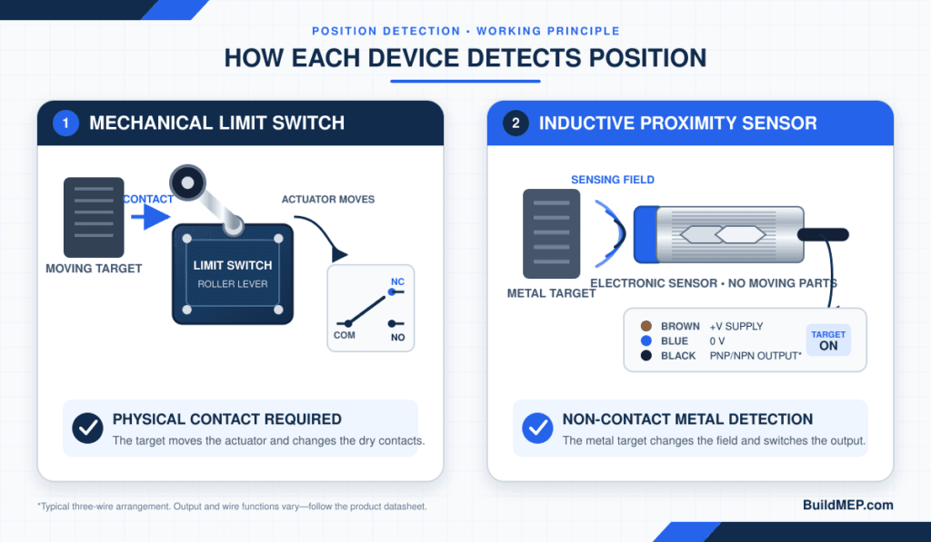
A limit switch is an electromechanical control device that changes the state of one or more electrical contacts when an external object moves its actuator.
The actuator may be a:
- Plunger
- Roller plunger
- Roller lever
- Adjustable lever
- Rod or whisker
- Rotary head
- Fork or specialised operating head
When the machine component reaches the switch, it pushes or rotates the actuator. The internal mechanism then changes the contact state. A normally open contact may close, a normally closed contact may open, or both may change in a changeover arrangement.
The word limit comes from one of its common uses: confirming that equipment has reached the end or limit of its permitted travel. However, limit switches are also used for presence detection, sequencing, interlocking and position feedback.
Limit switch working principle
A typical operating sequence is:
- A moving machine component approaches the switch.
- It contacts the actuator head.
- The actuator transfers movement to the internal mechanism.
- The contacts change state after the operating point is reached.
- The control circuit, PLC or BMS input detects the new state.
- When the object moves away, the switch returns after reaching its release point.
The distance between the operating and release positions is part of the switch’s differential travel. The mechanism also requires suitable pre-travel, overtravel and return movement. Incorrect cam geometry or excessive force can damage the head, shaft or internal mechanism.
Typical limit-switch contact arrangements
Mechanical limit switches commonly provide:
- 1 NO: one normally open contact
- 1 NC: one normally closed contact
- 1 NO + 1 NC: separate or changeover contacts
- 2 NC: often found in certain interlocking arrangements
- Multiple-pole contact blocks for more complex control functions
“Normally” describes the contact state when the actuator is not operated. Always verify whether the schematic is shown in the normal, de-energised and unactuated state.
Snap-action and slow-action contacts
A snap-action mechanism changes the contacts rapidly after the actuator reaches a defined point. This helps produce a repeatable switching action that is less dependent on the actuator’s movement speed.
A slow-action contact follows the actuator movement more directly. This arrangement may be required in particular control or safety-switch designs.
The selection must be based on the circuit duty and manufacturer’s operating diagram, not only the external actuator style.
What is a proximity sensor?
A proximity sensor is a sensor that detects the presence or approach of a target without the target having to interact with the sensor mechanically.
It is a device that transforms a change in an electromagnetic field, capacitance, light, sound or magnetic field into an electrical output. Since this sensing operation is non-contact, there is generally no mechanical wear between the sensing face and the target.
Proximity Sensor is the name of a family of devices. It is not limited to just the common threaded cylindrical inductive sensor that is used in so many comparison pictures.
IEC 60947-5-2 covers proximity switches in various categories, such as inductive, capacitive, ultrasonic, photoelectric and non-mechanical magnetic devices.
Main types of proximity sensors

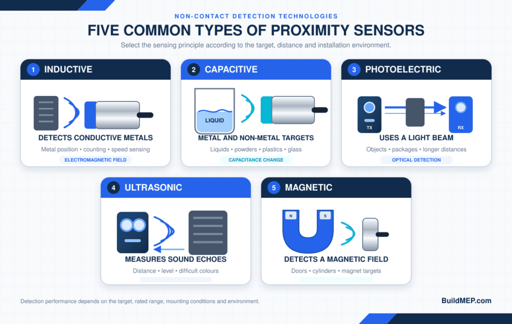
1. Inductive proximity sensor
An electromagnetic field is created at the sensor face of an inductive proximity sensor. Upon entering the field, the conductive metal target alters the oscillator condition and the sensor alters its output.
Ideal for: metal targets (such as gear teeth, brackets, machine slides, steel doors and conveyor parts).
Note: It is only able to sense metal, and the usable sensing distance will vary based on the target metal, size and shape. Normally the rated distance is determined with a given standard target. A shorter effective range can be achieved when stainless steel, brass, aluminium and other metals are used as the casing material unless the sensor is specifically corrected by a factor or has factor-1 characteristic.
2. Capacitive proximity sensor
A capacitive sensor changes in capacitance when the capacitance of the sensing face changes. It is able to detect conductive and non-conductive materials.
Specially adapted for: plastics, glass, powders, grains and liquids, including some level-detection applications through a non-metallic container wall.
Humidity, product build-up, container wall thickness and the variation of the product’s dielectric properties can impact detection, important limitation. Sensitivity adjustment and application testing is common.
3. Photoelectric sensor
A light transmitter and receiver are used in a photoelectric sensor. Typical method is through-beam, retro-reflective and diffuse reflective detection.
Ideal for: long range sensing, small objects, packaging lines and targets for which physical contact isn’t desired.
Significant restriction: performance may be affected by the dust, the condensation, the reflectivity of the target, the background, and the contamination of the lens. The correct setup of the optical system is important.
4. Ultrasonic proximity sensor
An ultrasonic sensor sends out sound waves and measures the reflected sound.
Good for: Items that have challenging colors or optical reflectivity, and for some distance or level applications.
There is a blind zone of the sensor to take note of, and it can be influenced by the angle of the target, air movement, temperature, foam and bad sound-reflecting surfaces.
5. Magnetic proximity sensor
Magnetic sensors are based upon a range of technologies including reed switches and solid-state sensing elements.
Recommended for: detecting the position of a pneumatic-cylinder piston, door position or wherever a magnet can be attached to the moving component.
Note: The required magnetic field must be applied to the target or actuator and nearby magnetic materials or fields can affect operation.
Limit switch vs proximity sensor: detailed differences
1. Physical contact
A limit switch must have contact and operating force. The direction of approach of the target, cam or mechanism should be acceptable and the travel required must not exceed the mechanical limits and should be sufficient.
Proximity sensor detects within a sensing zone. This eliminates impact between the target and sensing face during normal operation. Mounting protection and proper stand-off distance are still important though, as the target can still damage the sensor through mechanical mean
2. Service life
The mechanical operation and electrical load both have an impact on limit switch life. Contact erosion can also happen during load changes (inductive loads) or when there is a high inrush current, even if the mechanical body is functioning properly.
Unlike mechanically operated proximity sensors, there is no mechanical operating output contact in a solid-state proximity sensor, so the life of the sensing cycle is not typically limited by output contact wear. It is a plus when used in high-cycle applications. Does not make the device failure-proof – still the possibility of service life shortening due to temperature, vibration, cable damages, supply transients, ingress and incorrect loading.
3. Switching speed and frequency
The speed difference may be insignificant for a slow actuator, valve or door. When counting fast-moving parts or detecting gear teeth, the change of frequency may make all the difference.
Datasheet for proximity sensors may include the response time or switching frequency. The permitted operating speed, permitted operating frequency or permitted mechanical/electrical cycles are stated on the limit-switch datasheet. The frequency of the required machine should be compared to the machine ratings of the actual machine and a reasonable engineering margin added.
4. Repeatability and precision
When properly mounted, a proximity sensor will typically switch with very little or no backlash of the actuator. The switching point may vary depending on the target material, its mounting conditions, temperature, and voltage, and its real switching point can be different.
A good precision limit switch can also offer good repeatability, but over time mechanical play, cam wear, and/or the deformation of the actuator or movement of it during mounting could cause a change in the operating point.
Don’t be misled: repeatability is not the same as the accuracy of the measurement. A conventional discrete sensor is only automatically a precision displacement-measuring instrument, and not an ON/OFF sensor.
5. Sensing distance
The non-contact sensing distance for a limit switch is 0.The non-contact sensing distance of a limit switch is 0. The target needs to get to the actuator and the actuator needs to travel the required distance.
Distance range of proximity sensor varies according to the technology and model. The application distance for an inductive device can be less than the nominal or rated sensing distance. For instance, Omron’s technical guidance states, for the referenced sensor range, a stable set distance of about 70% to 80% of the normal rated sensing distance. Do not rely on the maximum nominal detection distance, but use the manufacturer’s guaranteed or operating distance.
6. Electrical output
This is one of the most important practical differences.
Potential free contacts are typically available from a mechanical limit switch. Subject to its utilization category and ratings, the contact can be wired into different control voltages.
Proximity sensors typically have an electrical output and require a suitable power supply and input circuit. Common versions include:
- Three-wire DC PNP
- Three-wire DC NPN
- Two-wire DC
- Two-wire AC
- Two-wire AC/DC
- Four-wire complementary NO/NC
- Push-pull output
- The switching amplifier output from NAMUR.
- IO-Link-enabled variants
The operating voltage, maximum load current, residual voltage, leakage current, short circuit protection and voltage drop of electronic outputs have limitations. These details may play a role in the proper operation of the sensor with the PLC or BMS DIO.
7. Load switching capability
It should be noted that a limit switch may have a higher switching rating than a small solid state sensor, but that does not mean that a load of that current may be switched.
The maximum rating allowed is a function of:
- AC or DC voltage
- Resistive or inductive load
- Utilization category
- Inrush current
- Switching frequency
- Required electrical life
Typically a proximity sensor is meant to be connected to a PLC input, relay input interface, etc., which is a low current load. Connecting a solenoid or a contactor coil, motor or lamp just because its steady state current is below the sensor’s maximum output current is not suitable. Verify the inrush and suppression requirements and the actual load characteristic. If necessary use an interposing relay or appropriate interface module.
8. Environmental resistance
Not all proximity sensors are better in all dirty/harsh environments.
When there is oil, water or target colour that would affect an optical sensor, the inductive sensor can do a very good job. The lens of a photoelectric sensor can become coated, which can be harmful to the sensor. Moisture and/or material accumulation can cause a capacitive sensor to mis-respond. A mechanical switch with an appropriate sealed enclosure can be very rugged in heavy industrial applications.
Compare:
- IP or NEMA enclosure rating
- Ambient and storage temperature
- Shock and vibration rating
- Oil and chemical resistance
- UV exposure
- Washdown or hygienic requirements
- Hazardous-area approvals, where applicable
- Cable and connector protection
The housing rating only applies when the device is installed as specified, including its cable entry, connector and mating components.
9. Maintenance
Limit switches require periodic inspection for:
- Loose mounting
- Worn rollers or levers
- Bent actuators
- Damaged cams
- Excessive overtravel
- Water entry
- Loose terminals
- Contact deterioration
While typically less mechanically demanding, proximity sensors still need to be inspected:
- Correct stand-off distance
- Loose locknuts or brackets
- Impact damage
- Metal chips on inductive sensing faces
- Product build-up on capacitive sensors
- Dirty photoelectric lenses or reflectors
- Cable and connector condition
- Mutual interference between adjacent sensors
“Non-contact” means reduced wear, not zero maintenance.
10. Initial and lifecycle cost
The purchase cost of a basic limit switch is typically less. However, installation can sometimes be accomplished with the use of a cam, bracket, guarded actuator path or additional mechanical adjustment.
A proximity sensor will require a compatible input and power supply and typically be more expensive. Ideal for a high cycle machine due to reduced wear and downtime, it could offer a lower lifecycle cost.
The price of the devices is not the right comparison. Add installs, brackets, relays to interface, replacement frequency, downtime, and maintenance access.

Wiring differences engineers must understand
Typical limit-switch wiring
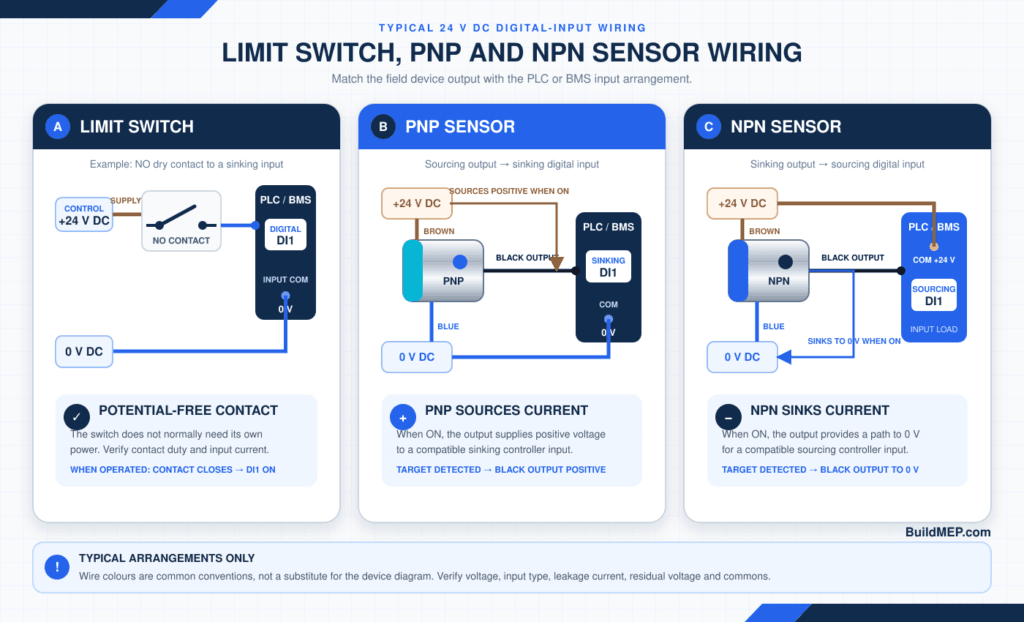
A dry-contact limit switch can commonly be wired between a control supply and a digital input, subject to the input design and switch rating.
For status monitoring, an NC contact can offer a limited form of fail awareness because an open wire and an operated contact can both remove the signal. However, this does not by itself create a safety circuit or provide full diagnostic coverage.
Typical three-wire DC proximity sensor colours
Many IEC-style sensor cables use:
| Conductor | Common function |
| Brown | Positive supply |
| Blue | 0 V DC |
| Black | Switching output |
| White | Second or complementary output, when provided |
This colour arrangement is common, but it must never replace the model-specific wiring diagram.
PNP vs NPN sensor output
A PNP output sources positive voltage/current to the input when ON. It is commonly used with a sinking digital input.
An NPN output sinks current toward 0 V when ON. It is commonly used with a sourcing digital input.
The sensor and controller input must be electrically compatible. Before purchasing, check:
- Controller input type: sinking, sourcing or configurable
- Sensor supply voltage
- ON-state voltage or residual voltage
- OFF-state leakage current
- Minimum and maximum input current
- Common 0 V/reference requirements
- Cable length and voltage-drop limitations
NO and NC do not always mean dry contacts
With a proximity sensor:
- NO output: normally OFF; turns ON when the target is detected
- NC output: normally ON; turns OFF when the target is detected
These terms describe electronic output logic. They do not necessarily indicate three relay terminals marked COM, NO and NC.
Two-wire sensor caution
A two-wire electronic sensor is connected in series with the load and normally draws a small current even when OFF. It also retains some voltage when ON. The resulting leakage current and residual voltage can cause:
- A sensitive PLC or BMS input to remain falsely active
- A relay or contactor to chatter or fail to release
- Insufficient voltage across the load
Check the complete input circuit. A bleeder resistor, interface relay or different sensor type may be required, but any modification should follow the equipment manufacturer’s guidance.

Flush vs non-flush inductive sensor mounting
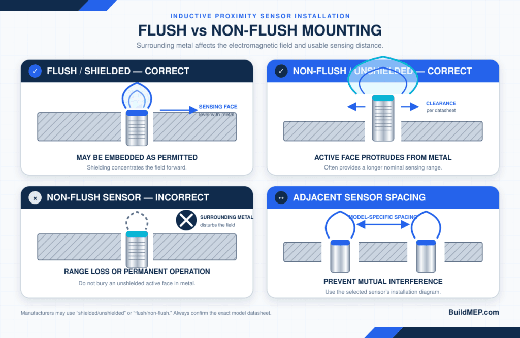
Inductive proximity sensors can be flush/shielded or non-flush/unshielded, depending on design.
- A flush-mount sensor can generally be embedded in surrounding metal up to its sensing face, as permitted by the datasheet.
- A non-flush sensor needs clearance around the active face because its field extends from the sides.
Non-flush designs often provide a longer sensing distance for the same body diameter, while flush devices benefit from greater mechanical protection. Required clearances between the sensor and surrounding metal—and between adjacent sensors—are model-specific.
Ignoring these distances can reduce sensing range, cause permanent activation or create mutual interference. Follow the mounting diagram supplied with the selected device.
Practical selection guide
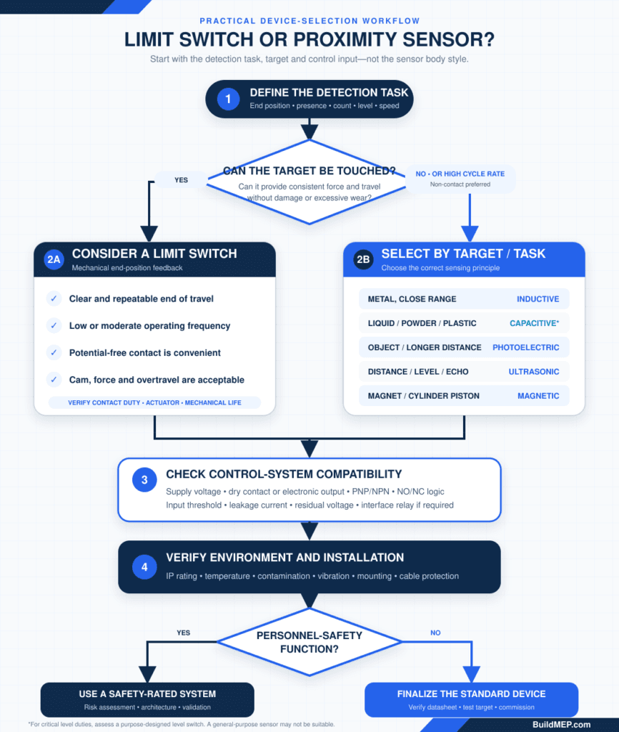
Use the following sequence rather than choosing only by appearance or price.
Step 1: Define the detection task
Decide whether you need to detect:
- End of travel
- Presence or absence
- Part count
- Rotational speed
- Door or guard position
- Product level
- Cylinder piston position
- A precise reference position
Also decide what must happen if the sensor fails or the cable breaks.
Step 2: Identify the target
Record:
- Material
- Size and shape
- Surface finish or colour
- Movement direction
- Approach speed
- Available operating force
- Distance from the mounting point
For an inductive sensor, the target’s metal type and dimensions are particularly important.
Step 3: Decide whether contact is acceptable
Contact may be unacceptable if the target is:
- Fragile
- Very small
- Moving quickly
- Hot
- Wet or contaminated
- Unable to provide consistent operating force
- Likely to damage the switch through impact
If positive mechanical end-position confirmation is more useful than non-contact detection, a limit switch may remain the better option.
Step 4: Check the environment
Document ambient temperature, moisture, washdown, dust, oil, chemicals, shock, vibration and hazardous-area classification. Do not select from IP rating alone.
Step 5: Check the control system
Confirm:
- Available supply voltage
- PLC/BMS digital-input type
- PNP or NPN compatibility
- Required NO or NC logic
- Input threshold
- Leakage-current tolerance
- Cable length
- Connector standard
- Need for a relay interface
Step 6: Check speed and repeatability
Calculate the required events per second. Compare this with the sensor’s response frequency and the PLC input filter or scan time. A fast sensor connected to a slow filtered input can still miss short events.
Step 7: Check mechanical installation
For a limit switch, verify cam shape, approach angle, operating travel, overtravel and return movement.
For a proximity sensor, verify sensing distance, assured operating range, mounting clearance, bracket rigidity, target alignment and protection against collision.
Step 8: Review safety requirements
If the device performs a personnel-safety function, stop treating it as an ordinary position input. Use safety-rated components and a validated safety architecture designed to the applicable machine-safety requirements.
Step 9: Compare lifecycle cost
Include commissioning effort, downtime, maintenance access, spare availability and replacement frequency—not only the unit price.

When should you choose a limit switch?
A limit switch is usually the practical choice when:
- The mechanism has a clear, repeatable end position
- Physical contact is acceptable
- Operating frequency is low or moderate
- A potential-free contact is preferred
- The control voltage may differ from typical sensor supplies
- A visible mechanical operating mechanism helps maintenance
- Low initial cost is important
- The target material is unsuitable for the available non-contact sensor
- A suitably rated direct-opening safety position switch is required as part of a properly engineered safety function
Typical applications
- Valve or damper end-position feedback
- Hoist and crane travel limits
- Machine-slide end position
- Conveyor stop position
- Access-door status
- Lift or gate mechanisms
- Packaging-machine mechanical sequencing
- HVAC actuator auxiliary feedback
For fire and smoke dampers, lifts, cranes or safety interlocks, use only devices and system arrangements approved for the specific duty. A general-purpose limit switch is not automatically suitable.
When should you choose a proximity sensor?
A proximity sensor is usually the better choice when:
- The target should not be touched
- Switching frequency is high
- Long mechanical life is important
- Accurate repeatability is required
- The target is small or moving quickly
- The environment would rapidly wear a mechanical actuator
- Detection must take place before physical contact
- Compact mounting is required
Typical applications
- Metal-part detection on a conveyor
- Gear-tooth or shaft-speed monitoring
- CNC machine position sensing
- Automated assembly lines
- Packaging count and presence detection
- Pneumatic-cylinder piston detection
- Product level through a non-metallic wall
- Door, gate or equipment-position feedback
Three practical examples
Example 1: Motorised HVAC valve end position
The requirement is to confirm that a slowly moving valve has reached fully open.
A built-in or external mechanical auxiliary/limit switch is often the simplest solution because movement is slow, a dry contact is convenient for a BMS digital input, and the end stop provides definite mechanical operation.
Before selection, verify the actuator manufacturer’s approved auxiliary-switch arrangement, contact rating and adjustment method. Do not improvise a bracket that affects actuator travel or warranty.
Example 2: Counting steel brackets on a fast conveyor
The target is steel, the cycle rate is high and contact would cause wear.
An inductive proximity sensor is normally appropriate. Select the body size and sensing distance using the actual target material and mounting arrangement. Check switching frequency against the maximum conveyor speed and minimum gap between parts.
Example 3: Detecting liquid through a plastic tank wall
The target is non-metallic and must be detected without entering the tank.
A capacitive proximity sensor may work, subject to wall thickness, liquid dielectric properties, moisture and build-up. Test the actual tank and product. If stable point-level detection is safety-critical or process-critical, consider a purpose-designed level switch instead of a general-purpose proximity sensor.
Safety interlocks: an essential warning
A normal limit switch or proximity sensor should not be assumed suitable for personnel protection.
Safety-related guard monitoring may require:
- A safety-rated position switch or safety sensor
- Direct-opening action where applicable
- Coded actuation or protection against simple bypassing
- Redundant channels
- Fault detection
- A safety relay or safety PLC
- Defined Performance Level or SIL
- Correct installation to prevent defeat
- Validation of the complete safety function
The component alone does not determine the achieved safety level. Risk assessment, circuit architecture, diagnostic coverage, common-cause failures, installation and validation all matter.

Common selection mistakes
Mistake 1: Treating every cylindrical sensor as equivalent
Two M18 sensors may have different sensing distances, mounting requirements, supply voltages, outputs, switching frequencies and connector pinouts.
Mistake 2: Ordering PNP or NPN without checking the controller input
The wrong output type can prevent the input from changing state or create an incorrect circuit reference.
Mistake 3: Using nominal sensing distance as the working clearance
Stable operating distance must include target tolerance, temperature, vibration, voltage and mounting conditions.
Mistake 4: Ignoring target material
An inductive sensor’s response to stainless steel or aluminium may differ significantly from its response to the standard steel target.
Mistake 5: Switching a coil directly without checking inrush and suppression
Steady-state current alone is not enough. The output may fail because of inductive energy or transient voltage.
Mistake 6: Mounting a non-flush sensor inside metal
Surrounding metal can attenuate the field or keep the sensor continuously operated.
Mistake 7: Assuming non-contact means maintenance-free
Loose brackets, damaged cables, build-up and impact remain common causes of failure.
Mistake 8: Using a general-purpose device for a safety function
Ordinary status feedback and safety interlocking are different engineering duties.
Final decision table
| Application requirement | Preferred starting point | Reason |
| Slow mechanical end-of-travel | Limit switch | Definite operation and simple dry contact |
| Fast metal-part counting | Inductive sensor | High switching frequency and no contact wear |
| Plastic, powder or liquid detection | Capacitive sensor | Can detect non-metallic materials |
| Longer-range object detection | Photoelectric or ultrasonic sensor | Greater range than typical inductive devices |
| Pneumatic-cylinder piston position | Magnetic sensor | Detects the piston magnet through the cylinder wall |
| Existing circuit needs potential-free contacts | Limit switch or sensor plus interface relay | Matches the control-input requirement |
| High-cycle repetitive machinery | Proximity sensor | Reduced mechanical wear |
| Safety guard monitoring | Safety-rated switch/sensor and safety system | Requires a validated safety function |
| Dirty, oily metal target | Sealed inductive sensor may suit | Non-contact metal detection; verify environmental rating |
| Mechanism with severe impact or misalignment | Review application geometry first | Either technology can fail if mechanically abused |
Frequently asked questions
Is a proximity sensor better than a limit switch?
Not universally. A proximity sensor offers non-contact operation, high speed and low mechanical wear. A limit switch offers simple contact logic, definite mechanical actuation and often lower initial cost. The application determines which is better.
Can a proximity sensor replace a limit switch?
Often yes, but not as a direct one-for-one replacement. You must check target material, sensing distance, power supply, PNP/NPN or two-wire output, controller input compatibility, mounting and safety requirements.
Can a limit switch be connected directly to a PLC?
Usually, if the contact rating and PLC input circuit are compatible. Confirm control voltage, input current, common arrangement and wetting-current requirements. Contact protection or an interface relay may be necessary in some applications.
Does an inductive proximity sensor detect all metals?
It detects conductive metals, but sensing distance can vary with material and target size. Standard inductive sensors often detect mild steel at a greater distance than aluminium, brass or some stainless steels. Check the manufacturer’s reduction or correction factors.
Can an inductive sensor detect plastic?
No, not directly. Use a capacitive, photoelectric, ultrasonic or other sensor suitable for the target and application.
What is the difference between PNP and NPN sensors?
A PNP output sources current to the load when ON; an NPN output sinks current when ON. The sensor output must match the controller’s digital-input arrangement.
Do proximity sensors have NO and NC contacts?
They can have NO or NC output behaviour, but most do not provide mechanical dry contacts. NO and NC usually describe whether the electronic output is ON or OFF when the target is absent.
Can a proximity sensor switch a contactor directly?
Only if the exact sensor output is rated for the contactor coil’s voltage, steady current, inrush and inductive load—and suitable suppression is provided. In many cases, a compatible interface relay is the safer engineering solution.
Which sensor is best for harsh environments?
There is no universal answer. A sealed inductive sensor may perform well around oil and metal debris, while a heavy-duty sealed limit switch may be better where positive mechanical operation is needed. Compare environmental ratings, materials and application conditions.
Can a normal limit switch be used as a safety interlock?
Do not assume so. Personnel-safety functions require appropriately rated components and a safety circuit designed and validated to the applicable requirements.
Conclusion
The big difference is simple: A proximity sensor detects without mechanical contact, a limit switch mechanically actuates. But when it comes to engineering, there’s more than just a price and speed comparison.
Use a limit switch if you require definite end of travel operation, dry contacts and a cost-effective solution for relatively slow moving systems. Use a proximity sensor when non-contact detection, high cycle rate, compact size and/or reduced mechanical wear are critical.
Before ordering either device, check the target, sensing distance, operating frequency, environment, output type, electrical load, mounting arrangement and safety function. Even if a correct sensor is connected to an incorrect input it is still the wrong solution.
BuildMEP practical rule: Start with the target and control input—not the sensor body style. After that, check the full manufacturer datasheet before making the ultimate choice.
Related BuildMEP resources
- Explore BuildMEP engineering tools
- How to Choose Valve Actuators for HVAC
- Siemens GCA166.1E vs GCA161.1E comparison
- Electrical Engineering guides
Technical references
- IEC 60947-5-1:2024 — Electromechanical control circuit devices
- IEC 60947-5-2:2019 — Proximity switches
- Omron — Proximity Sensors Technical Guide: Overview
- Omron — Proximity Sensors Technical Guide: Terms and output configurations
- Pepperl+Fuchs — Inductive sensor installation conditions
- Banner Engineering — PNP vs NPN outputs