



Risk Assessment for BTU Meter explained that installing or replacing a BTU meter may look like a straightforward mechanical task, but the work can involve several serious hazards. The chilled-water line may still be pressurized, the meter may be heavy, electrical supplies may remain live, and installing new thermowells may require drilling or welding.
The most important control is not a pair of gloves or a warning sign. It is proper planning: confirm the shutdown, identify every source of stored energy, isolate the correct section of pipework, drain it safely and prove that the line is at zero pressure before loosening a flange or opening the pipe.
This guide provides a practical risk assessment for installing or replacing an inline BTU meter and its temperature-sensor thermowells on a chilled-water system. It is written for HVAC contractors, MEP engineers, facilities teams, supervisors and HSE personnel who need a useful starting point for project documentation.
Important: This is a sample assessment, not a permit to work. It must be reviewed and adapted by a competent person for the actual site, equipment, pipe size, access conditions, local regulations, project HSE plan and approved method statement. The values in the risk table are illustrative. Your organisation’s approved risk matrix takes precedence.
What Does a BTU Meter Measure?
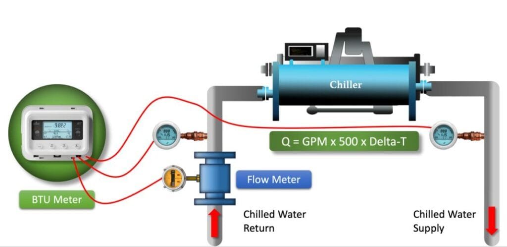
A BTU meter—more accurately called a thermal energy meter—calculates the heating or cooling energy transferred through a water circuit. A typical system has three main elements:
- A flow sensor that measures the water volume or mass flow
- A matched pair of temperature sensors installed in the supply and return lines
- A calculator or integrator that uses the flow and temperature difference to calculate energy
Because the calculation depends on all three elements, installation quality directly affects measurement accuracy. A flow sensor installed against the indicated direction, reversed temperature sensors, an incompletely inserted probe or an incorrect meter location can produce misleading readings even when the display appears normal.
Safety and workmanship therefore need to be managed together. The job is not complete simply because the pipe does not leak.
Risk Assessment for BTU Meter Scope
This assessment covers the typical sequence for:
- Delivering tools and materials to the work area
- Coordinating the shutdown and permits
- Isolating electrical and hydraulic energy
- Draining and depressurizing the chilled-water line
- Removing an existing inline BTU meter
- Installing a replacement meter
- Drilling and welding thermowell sockets on an isolated, drained pipe, where approved
- Installing the matched temperature sensors
- Routing power and communication cables
- Refilling, venting and restoring system pressure
- Leak testing, functional testing and BMS integration
- Reinstating insulation and cleaning the work area
It does not cover hot tapping or drilling into a live, pressurized pipe. Hot tapping requires a separate engineered procedure, purpose-designed equipment, a specialist contractor and a dedicated risk assessment. It must not be treated as an ordinary extension of this document.
People Who May Be Affected
The assessment should consider more than the technicians performing the work. People who may be affected include:
- HVAC technicians, pipefitters, welders and electricians
- Supervisors, commissioning engineers and HSE personnel
- Facility-management operators
- Other contractors working nearby
- Building occupants, visitors or members of the public
- Cleaning and security staff, particularly during night work
The work area should be isolated so that people who are not involved cannot enter the hazard zone.
Responsibilities
Project or Facilities Manager
- Approves the shutdown window and coordinates with affected building users
- Confirms that the correct system, branch and valves have been identified
- Ensures approved materials, competent personnel and suitable resources are available
Site Engineer or Supervisor
- Reviews the approved drawings, meter datasheet, method statement and risk assessment
- Conducts a pre-work inspection and toolbox talk
- Confirms that permits, isolations and access arrangements are in place
- Stops the work if site conditions differ from the assessment
- Coordinates refilling, testing and handover
HSE Officer
- Verifies the required permits and control measures
- Checks barricading, PPE, access, lighting, fire protection and housekeeping
- Monitors high-risk activities such as hot work and work at height
Technicians and Specialists
- Follow the approved method and manufacturer’s instructions
- Inspect tools and personal protective equipment before use
- Do not remove an isolation, bypass a control or change the work method without authorization
- Report leaks, damaged equipment, unexpected pressure or unsafe conditions immediately
Required Documents and Permits
The exact requirements vary by site, but the work pack will normally include:
- Approved method statement and project-specific risk assessment
- Latest approved shop drawing, schematic and valve-isolation plan
- BTU meter and temperature-sensor installation instructions
- Material approval or technical submittal
- Shutdown approval and permit to work
- Lockout/tagout or site isolation record
- Hot-work permit for drilling, welding, grinding or flame-producing work
- Work-at-height permit where required
- Inspection request and testing/commissioning forms
- Welding procedure and welder qualification where required by the project
- Safety data sheets for chemicals, sealants or insulation materials used
A permit-to-work system supports communication and coordination for higher-risk activities; it does not replace competent supervision or the physical controls at the workface.
Tools, Equipment and PPE
Typical tools and equipment may include:
- Correctly rated spanners, sockets and hand tools
- Calibrated torque wrench when a specified bolt torque applies
- Pipe-support or lifting equipment suitable for the meter weight
- Drain hose, collection container, wet vacuum and spill-control materials
- Pressure gauge or other approved method of proving zero pressure
- Welding machine and inspected leads, if hot work is approved
- Drilling equipment and guards suitable for the pipe material and task
- Fire blanket and correctly selected fire extinguisher
- Approved access platform, mobile tower or ladder for short-duration light work
- Adequate task lighting and, where required, low-voltage lighting
- Barricades, warning signs and floor protection
- Electrical test equipment appropriate to the circuit
Minimum PPE is normally a safety helmet, safety footwear, suitable gloves, safety glasses and workwear. Face protection, hearing protection, welding PPE, respiratory protection, fall protection or chemical-resistant PPE may also be required following the site assessment.
PPE is the final layer of protection. It should not be used as a substitute for isolation, depressurization, suitable access equipment or proper lifting arrangements.
How the 5×5 Risk Matrix Works
This example uses a five-point scale for likelihood and severity.
Likelihood
| Rating | Description | Typical meaning |
|---|---|---|
| 1 | Rare | Not expected during the task |
| 2 | Unlikely | Could occur, but not under normal controlled conditions |
| 3 | Possible | May occur during the work |
| 4 | Likely | Expected to occur in some circumstances |
| 5 | Almost certain | Expected repeatedly or without effective controls |
Severity
| Rating | Description | Typical consequence |
| 1 | Insignificant | No injury or negligible damage |
| 2 | Minor | First-aid injury or minor local damage |
| 3 | Moderate | Medical treatment, lost time or reportable damage |
| 4 | Major | Serious injury, major damage or significant service interruption |
| 5 | Catastrophic | Fatality, permanent disability or multiple serious injuries |
Risk score = Likelihood × Severity
| Score | Example classification | Required response |
| 1–4 | Low | Maintain controls and supervise normally |
| 5–9 | Moderate | Improve controls where practicable and monitor the task |
| 10–16 | High | Do not start until additional controls reduce the risk |
| 17–25 | Extreme | Stop the activity; revise the work method and obtain approval |
These bands are an example only. Use the matrix approved for your project.
Detailed BTU Meter and Thermowell Installation Risk Assessment
The initial score represents the estimated risk before the listed controls are applied. The residual score represents the expected risk after the controls are implemented and verified.
| Activity | Main hazards and possible consequences | Initial risk L×S | Required control measures | Residual risk L×S |
| Site arrival, induction and work-area setup | Unfamiliar access, collision with site traffic, slips, unauthorized entry | 3×3 = 9 | Complete site induction; sign in; confirm emergency arrangements; inspect the route and work area; install barriers and warning signs; maintain safe access for others | 1×3 = 3 |
| Moving the meter, valves, fittings and equipment | Back strain, crushed fingers or feet, dropped load, damage to calibrated equipment | 3×3 = 9 | Check item weight before lifting; use a trolley, chain block or suitable lifting aid; plan the route; use team lifting only within site limits; keep hands clear of pinch points; wear safety footwear and gloves | 1×3 = 3 |
| Accessing high-level pipework | Fall from ladder or platform, dropped tools, injury to people below | 3×5 = 15 | Use a suitable inspected platform or scaffold; obtain the required permit; keep both hands available when climbing; secure tools; establish an exclusion zone below; use fall protection where the site assessment requires it | 1×5 = 5 |
| Electrical isolation of meter, panel or nearby equipment | Electric shock, arc event, short circuit, unexpected equipment operation | 3×4 = 12 | Identify all electrical sources; isolate by an authorized person; apply lockout/tagout; prove dead using an approved test method; protect exposed conductors; keep electrical equipment away from draining water | 1×4 = 4 |
| Chilled-water system isolation | Pressurized water release, flooding, impact injury, interruption to occupied areas or critical equipment | 4×5 = 20 | Confirm the correct branch from approved drawings and physical tracing; notify affected parties; stop associated pumps where required; close and lock/tag the identified valves; allow the system to cool if necessary; verify that bypasses and cross-connections cannot repressurize the section | 1×5 = 5 |
| Draining and proving zero pressure | Sudden discharge, uncontrolled water, slippery floor, contact with treatment chemicals | 4×4 = 16 | Use the approved drain point and a secured hose; discharge to an authorized location; open vents carefully; monitor the pressure gauge; verify zero pressure at a safe point; provide spill containment; never rely only on the position of a valve handle | 1×4 = 4 |
| Disconnecting cables and temperature sensors | Electric shock, damaged sensors, sharp edges, trip hazards, loss of identification | 3×3 = 9 | Confirm isolation; label every cable and sensor before removal; photograph existing connections if permitted; protect loose cable ends; coil and secure cables away from access routes; handle matched sensors carefully | 1×3 = 3 |
| Loosening flanges and removing the existing meter | Trapped pressure, water release, falling meter, pinch points, cuts from corroded components | 4×4 = 16 | Reconfirm zero pressure; loosen the bolt furthest from the body first and cautiously check for trapped pressure; support the meter before removing bolts; use the correct tools; keep the body out of the potential release path; lower the meter using suitable equipment | 1×4 = 4 |
| Cutting, grinding, drilling or welding for thermowell sockets | Fire, burns, sparks, fumes, eye injury, noise, damage to hidden services | 4×5 = 20 | Confirm the pipe is isolated, drained and proven at zero pressure; obtain a hot-work permit; inspect the work location and opposite side of the surface; remove or protect combustible materials; provide ventilation, welding screens, fire blanket, extinguisher and fire watch; use inspected equipment and task-specific PPE | 1×5 = 5 |
| Installing the new flow sensor | Pinched fingers, poor flange alignment, damaged gasket, pipe strain, incorrect flow direction | 3×3 = 9 | Verify model, size, pressure/temperature rating and installation location; support the pipe and meter independently where required; align flanges without forcing them; fit the correct new gaskets; follow the indicated flow arrow; tighten bolts evenly to the approved sequence and torque | 1×3 = 3 |
| Installing thermowells and temperature sensors | Cuts, leaks, damaged threads, incomplete sensor insertion, inaccurate temperature measurement | 3×4 = 12 | Verify thermowell material, pressure rating, thread and insertion length; clean the connection; apply only the approved sealing method; install the matched sensor pair in the designated supply and return positions; ensure the probes are fully seated and secured according to the manufacturer | 1×4 = 4 |
| Routing power and communication cables | Trip hazards, damaged insulation, interference, incorrect termination, inaccessible future maintenance | 3×3 = 9 | Use the approved containment; segregate cables as required by the design; protect against sharp edges, heat and water; maintain bend radius; provide labels at both ends; keep junctions accessible; check polarity, shielding and termination requirements | 1×3 = 3 |
| Reinstating pipe insulation | Skin or respiratory irritation, cuts from cladding, concealed leaks, damaged vapour barrier | 3×2 = 6 | Confirm successful leak testing before closing insulation; use gloves, long sleeves, eye protection and any respiratory protection identified by the material assessment; seal the vapour barrier continuously; avoid covering displays, removable heads or service points contrary to manufacturer instructions | 1×2 = 2 |
| Refilling, venting and repressurizing | Water hammer, joint failure, uncontrolled leak, air lock, damage to the flow sensor | 4×4 = 16 | Clear personnel from vulnerable joints; open valves gradually in the approved sequence; vent trapped air; monitor pressure; inspect flanges, thermowells and drains continuously; stop and isolate immediately if leakage or abnormal noise occurs | 1×4 = 4 |
| Power-up, functional test and BMS connection | Unexpected electrical fault, incorrect readings, loss of control-network communication | 3×4 = 12 | Replace covers and verify safe termination before energizing; power up through the approved procedure; compare supply/return temperatures with an independent reference where practicable; verify flow direction, units, meter address and communication; record alarms and initial readings | 1×4 = 4 |
| Housekeeping and handover | Slips, sharp waste, blocked access, system left in an abnormal state | 3×2 = 6 | Remove water, metal swarf, welding waste, old gaskets and insulation debris; dispose of materials through approved routes; remove barriers only after the area is safe; confirm valve positions and equipment status with FM; close permits and submit records | 1×2 = 2 |
Safe Work Sequence
1. Confirm the Exact Scope
Before the shutdown starts, verify the meter tag, pipe size, flow direction, installation location and sensor arrangement against the approved drawing and manufacturer’s instructions. Confirm whether the flow sensor belongs on the supply or return pipe; this is product- and configuration-specific and should not be guessed.
Also compare the new meter with the existing installation:
- Nominal diameter and connection type
- Face-to-face dimension
- Pressure and temperature rating
- Required mounting orientation
- Power supply
- Temperature-sensor type and cable length
- Communication protocol and output configuration
- Available space for installation and maintenance
A meter that physically fits is not automatically a technically correct replacement.
2. Coordinate the Shutdown
Notify the facility-management team and affected occupants. Identify whether the shutdown will affect an AHU, FCU branch, tenant area, process load, data room or other critical service.
The shutdown plan should state:
- The equipment and branch being isolated
- The valves and electrical isolators to be operated
- Who is authorized to apply and remove locks or tags
- Where the system will be drained
- The expected shutdown duration
- The action to take if an isolation valve passes
- The procedure for refilling and returning the system to operation
Where isolation cannot be proven, the work must stop until a safe alternative is approved.
3. Isolate, Drain and Prove Zero Energy
Chilled-water pipework contains hydraulic energy even when the pump is stopped. Static pressure, trapped water and flow from a bypass or adjacent branch can still create a dangerous release.
Close the approved isolation valves, apply the site lockout/tagout procedure and drain the isolated section through a controlled route. Open an appropriate vent to release trapped pressure and assist draining. Verify zero pressure using the approved method before disturbing the pipe.
Do not assume that:
- A closed valve is fully sealing
- A stationary pressure-gauge needle is accurate
- A stopped pump means the line is depressurized
- A small initial drain flow means the pipe is empty
If water continues to enter the isolated section, treat the isolation as failed.
4. Remove the Existing Meter Safely
Label the temperature-sensor and communication cables before disconnecting them. Support the meter body before loosening the flange bolts, particularly on larger sizes.
Loosen the connection cautiously while standing away from the likely discharge path. If pressure, temperature or continuous flow is detected, retighten the connection where safe, stop the work and review the isolation.
Do not use the adjoining pipework as an uncontrolled support for a heavy meter. Forced flange alignment can introduce pipe stress and cause leakage after the system is repressurized.
5. Install Thermowell Connections
Where new welded sockets are required, confirm that the pipe is empty, isolated and safe for hot work. Protect nearby insulation, cables, valves, detectors and finished surfaces. The hot-work permit should define fire-watch duties and the post-work inspection period.
The thermowell must be compatible with the system pressure, temperature, pipe material, sensor diameter and required insertion depth. Its location should allow representative temperature measurement and safe future sensor removal.
Do not drill or weld a live pipe under this generic procedure. A proposed hot tap requires a separate engineering review and specialist method.
6. Fit the Flow Sensor Correctly
Before installation, check the arrow on the flow-sensor body. Install the sensor in the direction of normal system flow and in the position specified by the manufacturer.
Straight-pipe requirements, orientation, air-bubble sensitivity and strainer recommendations differ between meter technologies and models. Follow the exact installation manual rather than applying a generic “five diameters before and three diameters after” rule to every product.
Use new, correctly rated gaskets. Align the flanges without pulling them together using excessive bolt force. Tighten bolts progressively in a cross pattern where applicable and use the torque specified for the approved flange, gasket and bolt arrangement.
7. Install the Matched Temperature Sensors
Thermal-energy meters normally use a matched sensor pair. Keep that pair together and do not replace one sensor with a superficially similar probe unless the manufacturer explicitly permits it.
Confirm that:
- The supply and return sensors are in the correct pipes
- Each probe is fully inserted and properly secured
- The thermowell suits the sensor diameter and insertion length
- Sensor cables have not been shortened, extended or jointed unless permitted
- Cables are protected from heat, moisture, sharp edges and mechanical damage
- Any tamper seals required for billing or verification are installed
Reversed sensors may create a negative temperature difference or incorrect energy direction. An incompletely seated sensor can respond slowly and introduce measurement error.
8. Refill the System Slowly
Confirm that drains are closed, vents are controlled and all mechanical connections are complete. Refill gradually to reduce the risk of water hammer and to allow air to escape.
Inspect every disturbed connection while pressure increases:
- Flow-meter flanges or threaded joints
- Thermowell sockets and threads
- Drain and vent points
- Nearby joints that may have been stressed during the work
If leakage is found, do not tighten or dismantle a pressurized joint unless the approved procedure specifically allows a safe adjustment. Isolate and depressurize the section again.
9. Commission the Meter
After the mechanical installation passes its leak test, restore electrical power and complete the functional checks.
At minimum, record:
- Meter manufacturer, model and serial number
- Meter tag and physical location
- Initial energy and volume readings
- Flow rate and indicated flow direction
- Supply temperature, return temperature and temperature difference
- Engineering units
- Error codes or alarms
- M-Bus, Modbus, BACnet, pulse or other configured output
- Network address, baud rate and communication status where applicable
If the meter communicates with the BMS, confirm that the BMS points match the local display. A successful network connection does not prove that the supply and return sensors are installed correctly.
Stop-Work Conditions
Stop the activity and inform the supervisor if any of the following occurs:
- The pipe cannot be positively identified
- The isolation valve is passing or zero pressure cannot be proven
- The meter model, rating or installation location does not match the approved documents
- Unexpected hot water, pressure, chemicals or contaminated fluid is found
- Required permits, competent persons or fire controls are unavailable
- Pipe supports are damaged or the pipe moves when bolts are loosened
- The work area becomes unsafe due to water, poor lighting, ventilation or unauthorized access
- The actual work requires live hot tapping, although the approved method assumes a drained pipe
- A serious leak, electrical fault or abnormal system condition appears during restoration
Stopping at the right time is a control measure, not a failure to complete the job.
Quality Checks That Should Accompany the Risk Assessment
A risk assessment manages harm, but a separate inspection checklist should confirm the technical quality of the installation.
| Check | Acceptance point |
| Meter identification | Approved model, size, rating and serial number recorded |
| Flow direction | Body arrow matches normal system flow |
| Installation location | Supply or return position matches the selected meter configuration |
| Orientation | Complies with the manufacturer’s installation instructions |
| Flange or thread connection | Correct gasket/seal, alignment and approved tightening method |
| Temperature sensors | Correct matched pair, correct supply/return positions and full insertion |
| Cable installation | Protected, labelled, correctly terminated and accessible |
| Insulation | Vapour barrier restored without preventing access or overheating electronics |
| Leak test | No leakage at all disturbed joints at the approved test condition |
| Meter display | Flow, temperatures, temperature difference and energy direction are reasonable |
| BMS integration | All mapped points, units, addressing and communication verified |
| Records | Initial readings, photographs, permits and inspection forms completed |
Common Mistakes to Avoid
Using a Risk Table Without a Real Risk Score
Listing “low” likelihood beside an impact number is not a complete assessment. The table should define the scoring method, show the initial risk, identify effective controls and reassess the residual risk.
Treating PPE as the Main Control
Gloves and goggles cannot control a pressurized-water release. Isolation, lockout/tagout, controlled draining and proof of zero pressure come first.
Assuming All BTU Meters Need the Same Straight Length
Required upstream and downstream pipe conditions depend on the meter design and manufacturer. Use the exact product manual.
Mixing or Reversing Temperature Sensors
Matched sensor pairs should remain together. Clearly label supply and return sensors before removing the old meter and verify the new arrangement during commissioning.
Insulating Before Leak Testing
Closing the insulation too early can hide a small leak and force the team to remove completed work. Pressure restoration and inspection should be completed first.
Considering BMS Communication as Final Proof
A meter may communicate perfectly while reporting the wrong value due to reversed sensors, incorrect units, wrong pulse scaling or an unsuitable installation location. Compare the BMS points with the local meter display and the expected system condition.
Practical Pre-Start Checklist
Use this short check at the toolbox talk:
- Correct meter tag and pipe identified
- Approved drawing, datasheet and method statement available
- Shutdown and all required permits approved
- Affected personnel informed
- Electrical and hydraulic energy sources identified
- Lockout/tagout equipment available
- Drain route and spill controls prepared
- Zero-pressure verification method agreed
- Meter weight checked and lifting method arranged
- Access platform inspected where required
- Hot-work controls and fire watch ready where applicable
- Correct meter, matched sensors, thermowells, gaskets and fittings on site
- Calibrated or inspected tools available where required
- Work area barricaded and adequately lit
- Commissioning and BMS support coordinated
- Emergency and stop-work arrangements understood
Frequently Asked Questions
Can a BTU meter be replaced without draining the chilled-water system?
An inline meter normally requires the relevant pipe section to be isolated, depressurized and drained before a flanged or threaded connection is opened. The exact arrangement depends on the installed valves and meter design. Clamp-on ultrasonic equipment is different because its transducers are fitted externally, but any associated temperature-sensor work must still follow the approved method.
Is stopping the chilled-water pump enough to make the pipe safe?
No. A stopped pump does not remove static pressure or prevent flow from another pump, bypass or connected branch. The correct valves must be isolated and the work section must be drained, vented and proven at zero pressure.
Is a hot-work permit required for thermowell installation?
It is normally required when welding, grinding, flame cutting or another spark- or heat-producing process is used. Follow the site’s permit-to-work rules. Drilling may also require a specific permit or additional controls even where it is not classified as hot work.
Can the thermowell be installed by drilling a live pipe?
Not under a standard drained-pipe method. Work on a live pressurized pipe is a specialist hot-tapping activity requiring an engineered procedure, suitable fittings and equipment, competent specialists and a dedicated risk assessment.
Can one damaged temperature sensor be replaced on its own?
Do not assume so. Thermal-energy meters commonly use matched sensor pairs, and replacing only one sensor can affect accuracy or verification status. Follow the meter manufacturer’s instructions and applicable metering requirements.
Where should the BTU meter be installed: supply or return?
That depends on the meter model, order configuration and approved design. Some meters or calculators are configured for a specific installation side. Confirm the marked configuration and manufacturer’s instructions before installation.
How much straight pipe is required before and after the meter?
There is no reliable universal value for every BTU meter. The requirement depends on the flow-sensor technology, model and nearby disturbances such as bends, valves and pumps. Use the installation manual for the exact product.
What should be checked before handing the meter over?
Check for leaks, verify flow direction, confirm reasonable supply and return temperatures, verify the temperature difference and energy direction, record initial readings, clear alarms and compare BMS values with the local display.
Final Takeaway
A useful BTU meter risk assessment should reflect how the job will actually be carried out. The critical controls are positive system identification, coordinated shutdown, electrical and hydraulic isolation, controlled draining, proof of zero pressure, safe access, properly managed hot work and gradual repressurization.
Technical checks are equally important. Correct flow direction, installation side, sensor pairing, immersion, cable routing and commissioning determine whether the meter will provide reliable energy data after the work is completed.
Use this guide as a starting point, then adapt it to the project. Walk the area, involve the technicians, review the meter manual and update the assessment whenever the site conditions or work method change.
Download the templates.
Before submitting either document, replace the sample project information and risk ratings with the actual site details, approved matrix, responsible persons and control measures.
References and Further Guidance
- HSE: Managing risks and risk assessment at work
- HSE: Permit-to-work systems
- OSHA: Control of hazardous energy—lockout/tagout
- The approved installation manual for the exact BTU meter, flow sensor and temperature-sensor pair being installed
- The project HSE plan, approved drawings, specifications and local legal requirements